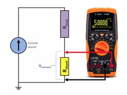
Basic concepts
To get started, we need to quickly review some basic concepts that will provide the common ground needed to better understand the following steps.
Direct current
Direct current is a unidirectional flow of electrons: electrons always move in the same direction, with an intensity that may also vary over time. A battery is the most common example of a direct current source.
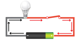
Two quantities describe what happens in a circuit of this type:
- the difference in electrical potential between the two electrodes (the two terminals of the battery) is called voltage;
- the amount of electrical charge flowing between the two electrodes is called current.
A comparison that helps fix these concepts is the hydraulic analogy: voltage is similar to the pressure of water inside a pipe, while current is similar to the flow rate, that is, the amount of water that actually flows.
Alternating current
In alternating current, the flow is not constant in a single direction, but consists of a succession of positive and negative pulses: the current continuously changes direction, following a regular pattern over time.
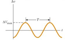
Some key concepts:
- the voltage of an alternating signal can be expressed in different ways: as peak value (the maximum reached by the waveform) or, more commonly, as RMS value (Root Mean Square), which is the value normally used to indicate the voltage of household electrical networks;
- the number of pulses per second is called frequency, and is measured in Hertz (Hz): later we will see that a few tens of Hertz can make the difference between correctly hearing a CW signal or no longer being able to receive it.
- the “standard” waveform of alternating current follows a curve called a sine wave.
The sine wave
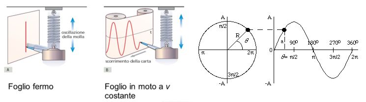
The sine wave is the graphical representation of oscillations: it is the shape that would be produced, for example, by the trace left by a pen attached to an oscillating spring, if a sheet of paper were moved underneath it at a constant speed.
It is a relatively simple signal to generate, but very difficult to obtain in a perfectly pure form: any real electronic circuit introduces imperfections, to a greater or lesser extent. Any alteration of the waveform compared with a pure sine wave is called distortion, and distortions almost always have negative effects on signal quality (we will return to this topic later when discussing harmonics).
Alternating current and radio
Alternating current and radio are intrinsically connected. The mechanism, in summary, is the following:
- the “radio” originates from an alternating current generated by the transmitter;
- this current is transferred to the antenna, which acts as a transducer;
- the antenna converts part of the energy of the electrical current into an electromagnetic field radiated into space;
- the electromagnetic field spreads from the antenna and propagates through space, reaching receivers.
Everything we will do while building the Pixie — generating a stable frequency, mixing it, amplifying it — ultimately serves the purpose of correctly producing and managing this alternating current.
Units of measurement
To describe these phenomena accurately, we need shared units of measurement:
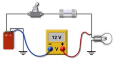
- voltage is measured in Volts (V);
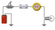
- the current flowing in a circuit is related to its resistance, and is measured in Amperes (A);
- resistance is measured in ohms (Ω);
- power is measured in Watts (W), and in direct current it is the product of Volts multiplied by Amperes.
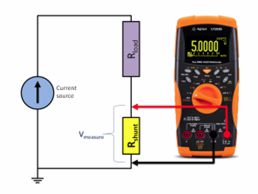
There are formulas that allow us to calculate one of these quantities when the others are known — the most important one, Ohm’s law, will be examined in detail when we discuss resistors.
Multiples and submultiples
Many of the units we will use (especially the Farad, the unit of measurement for capacitor capacitance) are, in practical electronics, either too large or too small to be used directly. For this reason, multiples and submultiples of the basic units are used by applying prefixes. It is useful to always keep in mind the relationship between prefixes: in electronics, prefixes normally differ by a factor of one thousand.
| Prefix | Symbol | Value |
|---|---|---|
| Tera | T | 1,000,000,000,000 |
| Giga | G | 1,000,000,000 |
| Mega | M | 1,000,000 |
| Kilo | k | 1,000 |
| Milli | m | 1/1,000 |
| Micro | µ | 1/1,000,000 |
| Nano | n | 1/1,000,000,000 |
| Pico | p | 1/1,000,000,000,000 |
These prefixes will appear constantly as we read the values printed on components (especially capacitors), so it is worth learning them well from the beginning (or keeping this table within reach).