People often tend to focus heavily on transmitter power, increasingly sensitive receivers, or technologically advanced equipment. However, as every radio amateur knows well, the true heart of any radio station – the element that more than any other determines the effectiveness of the system – remains the antenna.
A good antenna system can make the difference between a signal that travels thousands of kilometers and one that gets lost in background noise. Even with modest power, a well-designed and properly installed antenna can deliver surprising results.
HF
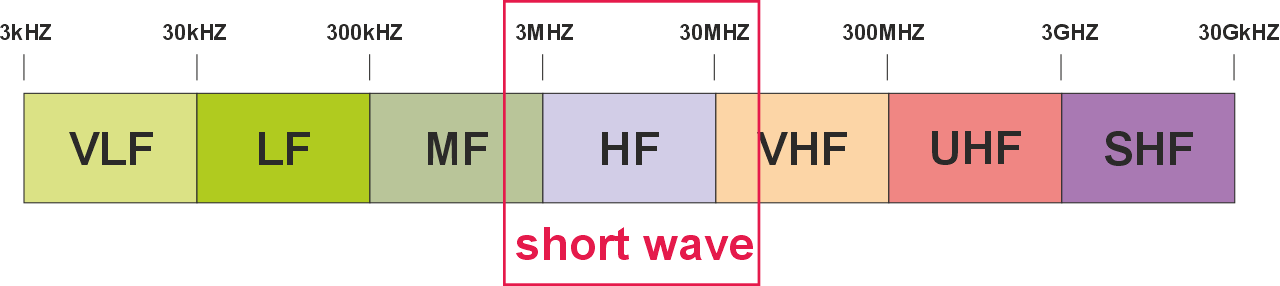
The HF bands (from 3 to 30 MHz) are the most fascinating playground of amateur radio, if only because they are the frequency range where it is possible to make contacts all over the world. On these frequencies, theory, manual skills, and a lot of experience – born from experimentation – coexist. My experience leads me to think that there is no “best antenna ever,” but rather the right one for your space, your goal, and your desire to experiment. The performance and efficiency of an antenna depend significantly on the characteristics of the environment in which it is installed.
Antennas, to work effectively, must be resonant on the frequencies for which they are used: only in this way can they transfer maximum energy from the transmitter to the ether and vice versa.
In the case of amateur bands, which practically cover the entire HF spectrum, this means that in principle you would need a dedicated antenna for each band, because each has a different wavelength and therefore requires a specific size of the radiating element. The simplest solution would be to install a dipole for each band, thus guaranteeing perfect resonance on each frequency. However, this choice involves a practical problem: the space required becomes enormous and is difficult to manage in a domestic station.
For this reason, compromises are used, building multiband antennas that, thanks to particular construction tricks or the use of traps and matching systems, can cover several bands with a single structure.
In this way, the footprint is reduced and good operational efficiency is maintained, while accepting some limitations compared to the ideal solution of a dedicated antenna for each band.
Wire antennas
If you have enough space available, a simple solution is to use wire antennas. As the name suggests, they are made with an electrical wire of adequate cross-section (at least 1.5 mm²). The conductivity of the material is important because it affects the efficiency of the antenna. Copper is excellent, aluminum is less good, while steel should be avoided.
This conductor is placed in space in such a way as to favor electromagnetic radiation. This simplicity is their strength. They do not require rigid structures, do not impose fixed geometries, and do not demand complex installations.
They are antennas that adapt to reality, not the other way around.
Adaptability
A wire antenna can be:
- stretched horizontally
- inclined
- bent into an L, V, or U shape
- run along a wall
- partially wrapped around supports
- suspended between trees, poles, balconies
Each variation changes impedance, radiation lobes, and bandwidth, but the antenna continues to work, often with more than respectable results. This allows you to exploit irregular spaces, small courtyards, complex roofs, or temporary environments.
Modularity
Wire antennas are “open systems”: you can add or remove elements without overturning everything.
- loading coils
- traps
- choke baluns
- impedance transformers
- counterpoises
- additional segments
Each modification is a controlled experiment. It is a didactic and scientific approach at the same time.
Minimum costs, maximum yield
A roll of electrical wire, a few insulators, and some cord: with just a few euros you can build an antenna that can cover several bands and provide DX contacts. This lowers the entry threshold and encourages continuous experimentation.
Perfect for temporary installations
Field days, portable activations, emergencies, improvised contests: a wire antenna can be installed in a few minutes and taken down just as quickly. It is the “trusted” antenna when you need to be on the air immediately: in my emergency communications kit I have two wire antennas of different sizes.
Tolerance for compromise
Wire antennas accept compromises without becoming unusable. Even when you cannot respect the ideal length or the optimal layout, a wire antenna:
- radiates
- receives
- allows communication
And even if you are not able to install them under ideal conditions, the results often surprise with efficiency and low noise.
An overview of the most common antennas
The classic dipole is the starting point for almost everything. Two symmetrical arms, center-fed, length equal to half a wavelength: it is the antenna that best represents the balance between theory and practice. It works well, is predictable, has manageable impedance, and offers excellent efficiency. Its only limit is space: to work at its best it needs to be installed fairly straight and at an adequate height. This means that a dipole for 80 m is about 40 m long.
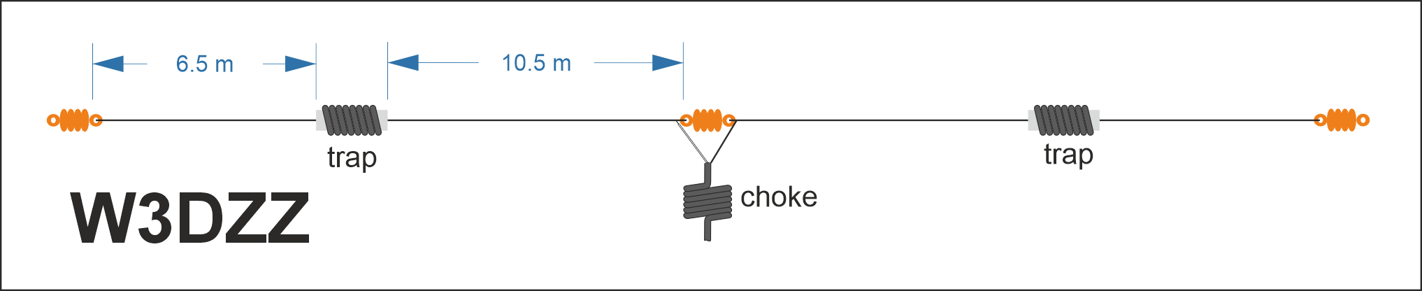
If, as is likely, this type of antenna is too bulky, you can use multiband wires. These are antennas that often use resonant circuits – called traps – to electrically alter the length of the antenna and allow it to resonate on multiple frequencies. In the diagram there is a classic antenna, the W3DZZ, which works on 3.5, 7, 14, 21, and 28 MHz and can be easily home-built. The choke at the feed point is usually a simple length of coaxial cable wound into turns in the air (or, even better, on a toroid), whose purpose is to balance the (unbalanced) cable to the (balanced) dipole.
The dipole can also be mounted as an inverted V: it is supported at the center at a high point, while the arms slope downwards. This geometry makes it more compact and easier to install, and at the same time gives it a pattern closer to omnidirectional. It is the field antenna par excellence: quick, effective, and forgiving of imperfections.
Another very common wire antenna is the End-Fed Half Wave (EFHW): it combines the resonance of the half-wave with the convenience of end feeding. With a suitable impedance transformer, it can be installed in countless ways: stretched, bent, in an L shape, zig-zag, along a wall. It is perfect for those who have irregular spaces or only one anchor point. Moreover, with traps or resonant segments, it easily becomes multiband. It only requires attention to common-mode currents, but for that it is enough to install a good choke.
The long wire is the “emergency” wire antenna, the one you throw out of the window or stretch between two trees when you need to be on the air immediately. It is not resonant, so it requires a tuner and a suitable counterpoise, but in return it offers total flexibility: any length, any shape, any context. Its behavior is less predictable, but precisely for this reason it is loved by experimenters and those who operate portable.
A historic antenna is the G5RV, a particular dipole designed to work on multiple bands thanks to a section of ladder line that acts as an adapter. It is an antenna that has made radio history and is still used in many fixed installations. Its variants, such as the ZS6BKW, optimize its behavior on some bands. It requires some care in laying the ladder line, but offers good multiband coverage.
A variant of the classic dipole is the Off Center Feed (OCF), which is based on a simple idea: shifting the feed point away from the center to exploit even and odd harmonics. With a 4:1 or 6:1 transformer, it becomes a very practical multiband antenna, capable of covering several frequencies without traps. It is easy to install and widely used in home stations. The only aspect to manage is the possible presence of common-mode currents, but again a choke solves the problem.
Less common in amateur radio, but always worth remembering, is the Terminated Two Wire Folded Dipole (T2FD): it is a folded dipole – two parallel wires spaced apart – the feed point at the center of one of the wires and terminated with a resistor at the center of the opposite one. This makes it less efficient, but extremely broadband and very quiet in reception. For these characteristics it is often used in military and professional contexts. It is not small, but it is reliable and predictable.
These antennas, so different from each other, share the same soul: the ability to adapt. The dipole is the pure form, the inverted V is practicality, the EFHW is modern versatility, the long wire is intelligent improvisation, the G5RV is multiband tradition, the OCF is harmonic optimization, the T2FD is wideband stability. They are all answers to a single question: how can I make a piece of wire work as well as possible in the space I have available? And it is precisely this question that makes wire antennas such fertile ground for the creativity of the radio amateur.
Volumetric
Unlike wire antennas (which develop mainly along a line), these antennas occupy a volume in space, exploiting surfaces, multiple elements, three-dimensional geometries, or self-supporting structures.
If wire antennas are the realm of simplicity and adaptability, volumetric antennas represent the other face of amateur radio: that of structure, controlled geometry, directivity, and pushed optimization. These are antennas that do not just “sit in space,” but shape it, intercept it, exploit it to concentrate or distribute electromagnetic energy in a precise way.
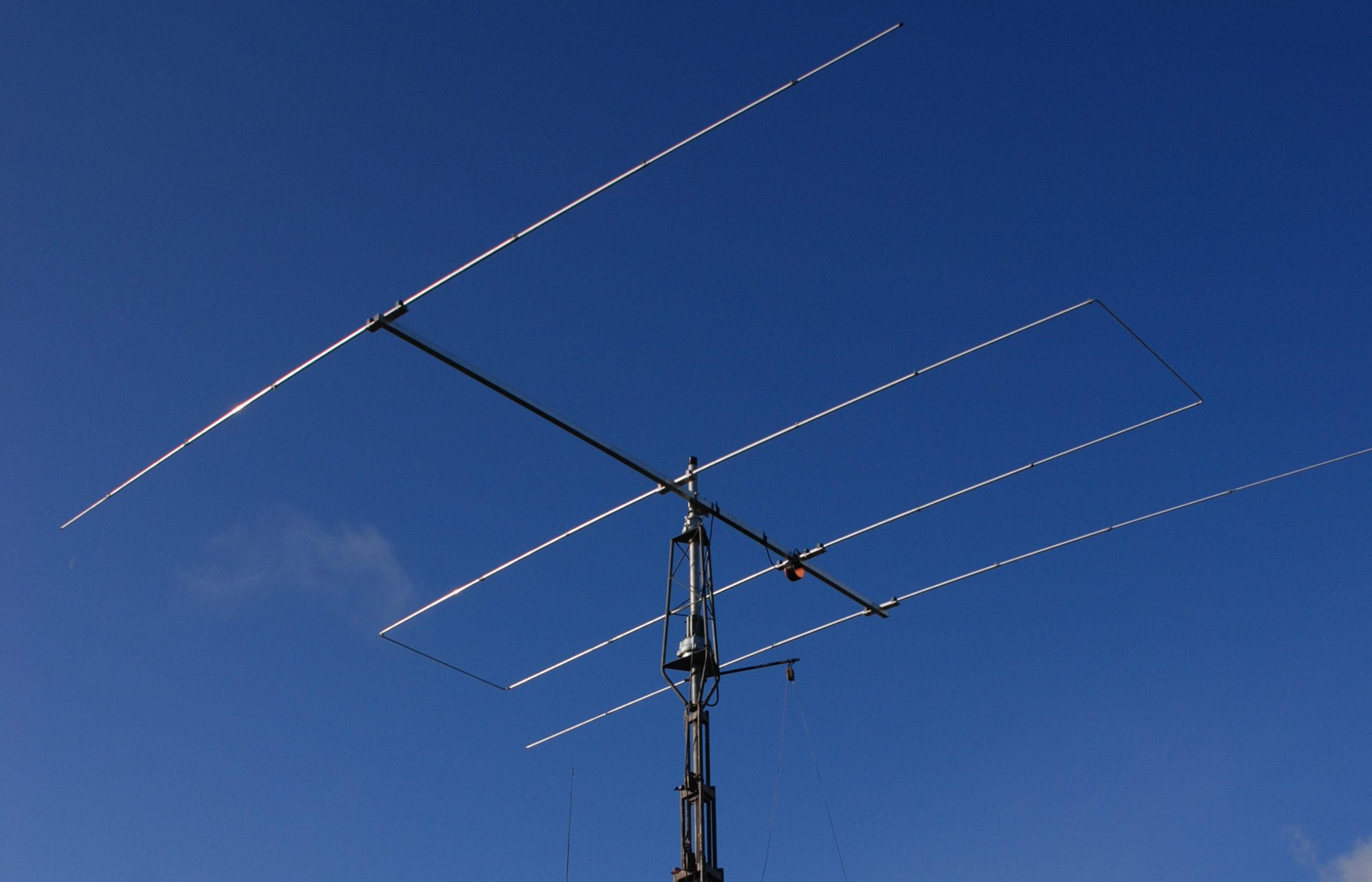
The first figure that comes to mind is the Yagi, perhaps the most iconic directive antenna. With its parallel elements – a driven dipole, a reflector, and a series of directors – it represents the radio amateur’s ability to shape the electromagnetic field. The Yagi is not just an antenna: it is a miniature engineering project. It offers gain, directivity, high front-to-back ratio, and an ability to “punch through the noise” that makes it indispensable for DX. It is the antenna for those who want to go far and know where to point.
Alongside the Yagi, but with a different philosophy, we find vertical antennas. These antennas use vertical polarization and a real or artificial ground plane. Their strength lies in operational simplicity combined with a low radiation angle, ideal for DX. A well‑installed vertical, with a good radial system, is a long‑distance communication machine. It requires no rotors, takes up very little horizontal space, and works well even in urban environments. It is the antenna of those who want efficiency and discretion.
Vertical antennas are generally multiband, implemented through resonant circuits (traps), and they require an appropriate ground plane, natural or artificial. There are also non‑resonant verticals, based on a relatively short vertical radiator (around 7 meters) that is not cut for any specific frequency. Feeding is provided through an impedance transformer, which allows a low standing‑wave ratio over a very wide frequency range. This approach makes it possible to cover a very broad spectrum, often from 3.5 MHz up to 30 MHz, without traps, without complex radials – but with an adeguate counterweight – and without mechanical complexity. This simplicity comes at a cost: efficiency is not comparable to that of a resonant vertical or dipole. While performance on the lower bands – especially 80 meters – is modest, my experience on the higher bands is more than positive: I use one for the WARC bands, and the results speak for themselves.
This category includes the Rybakov, better known as the fishing‑pole antenna, named after the support used to hold a piece of copper wire about 7.5 meters long and an unbalanced transformer (un‑un) with a 4:1 or 9:1 ratio (depending on the version).
Then there is an antenna that looks like it came out of a physics lab: the cubical quad (or simply, quad). Here the wire is no longer stretched in a line, but forms a square (or several squares) suspended in space. The quad is a Yagi “in three dimensions”: quieter, more efficient for the same boom length, and less sensitive to ground losses. It is an antenna that requires space and some construction skill, but it rewards you with elegant behavior and remarkable performance.
Another fascinating family is that of loops, which can be small, large, magnetic, self-supporting, or suspended. The magnetic loop, in particular, is a small masterpiece: a metal ring that, thanks to a variable capacitor, becomes a resonant antenna that is extremely selective. It is perfect for those with very little space, because it concentrates the magnetic field and reduces electrical noise. It is the antenna of the urban radio amateur who does not want to surrender to the limits of the apartment building. They have two limitations: extremely narrow tuning, which must be adjusted even for small frequency shifts, and very high voltages – thousands of volts – on the capacitor plates even with relatively low power.
Scaling up, we encounter log-periodic antennas, which look like Yagis but are not. Their geometry follows a logarithmic progression that allows them to cover a wide range of frequencies with a single structure. These are professional antennas, used in military, scientific, and broadcast fields, but also by radio amateurs who want a “do-it-all” directive without changing antenna for each band.
Where wire antennas accept compromises, volumetric antennas optimize. Where wire antennas are light and flexible, volumetric antennas are structured, directional, often ambitious.
 Info
InfoAn excellent overview of homebrewing techniques for various types of amateur radio antennas can be found on the website officinahf.
The title photo is by John Vooght