Serial communication
Communication
Communication is the heart of our hobby, but it is also a key element of every computing system, including modern radio equipment. Thanks to it, the central unit can communicate with peripherals and, within the same computer, the individual modules that compose it (such as CPU and memory).
There are two main families of communication: parallel and serial. In the early days of personal computers, parallel communication was very common because multiple bits are transferred simultaneously over dedicated data lines, making it conceptually simple and fast over short distances. For longer distances, serial communication is required.
Serial Communication
In serial communication, the bits that make up the transmitted data are sent sequentially, one at a time, over a single channel. The logic is similar to Morse code: each character is encoded into a sequence of signals by the transmitting station and decoded by the receiving station. Serial communication has been in use since the late nineteenth century in teleprinters, which used a 5-bit alphabet invented by Émile Baudot: from his name comes the unit baud, which represents the number of symbols transmitted per second. In a simple binary line, 1 baud corresponds to 1 bit/s.
The simplification on the electrical side comes at the cost of a significant increase in interface complexity: precise rules must be established so that the receiving station can correctly reconstruct the transmitted bit sequence.
Synchronous and Asynchronous Communication
The primary function of any serial protocol is synchronization between transmitter and receiver, which can be achieved in two different ways.
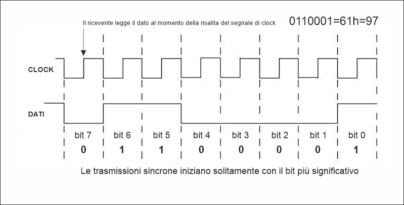
In synchronous transmission, bits are aligned to an auxiliary signal called a clock, which determines timing. Data is sent in groups called frames, and the receiver knows that at each rising edge of the clock there is a bit to read, making reconstruction relatively simple. This is mentioned only for completeness, because in our use cases asynchronous transmission is the one used.
Instead of relying on external references, synchronization elements between transmitter and receiver are embedded within the bit stream itself, eliminating the need for a dedicated clock line.
Asynchronous UART
The most common variant of asynchronous serial communication is the UART (Universal Asynchronous Receiver/Transmitter). Since, as mentioned above, there is no external reference, for two devices to “understand each other” they must share the same operating parameters, starting from the duration of each bit, defined by the baud rate.
The Frame
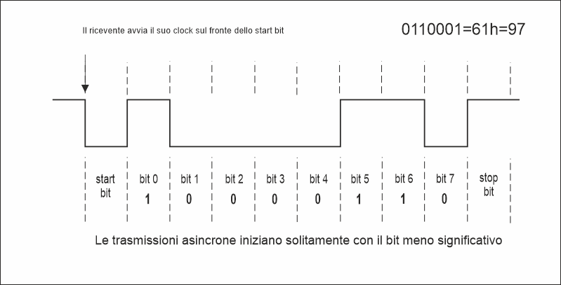
Equally important is the method used to transmit individual bits. Each byte is transmitted encapsulated in a frame, which allows the receiver to identify the start and end of the data. The line at rest is in a high logic level (“1”). Transmission follows this sequence: first the Start bit is sent, pulling the line low (0) and marking the beginning of transmission. Then come the data bits, typically 8 (5 in RTTY), transmitted from least significant bit (LSB) to most significant bit (MSB). Optionally, a parity bit may be added, calculated from the data bits and used to detect errors. The sequence ends with the Stop bit, which returns the line to the high level.
The start bit synchronizes the receiver, which then samples bits based on its internal clock. Synchronization is re-established for each character, so timing drift does not accumulate. However, asynchronous transmission is less efficient than synchronous transmission because part of the stream is used for synchronization.
Configuration
A serial port configuration is defined by four parameters that must match on both communicating devices. A single incorrect parameter can cause random characters, framing errors, or complete loss of communication, without the system providing clear diagnostic feedback.
| Parameter | Typical values | Notes |
| Baud rate | 1200, 2400, 4800, 9600, 19200, 38400, 57600, 115200 | 9600 baud is the most common in radio transceivers |
| Data bits | 7 or 8 (5 for RTTY) | 8 bits is the modern standard; 7 bits may be used in older equipment |
| Parity | None (N), Even (E), Odd (O) | Rarely used in modern applications |
| Stop bits | 1, 1.5, 2 | Usually 1 in modern applications, 1.5 for RTTY |
The compact notation summarizes all parameters in a string such as 9600 8N1: baud rate, data bits, parity, stop bits.
RS-232, TTL and LVTTL
The frame defines how bits are sent, but electrical parameters must also be defined. The choice depends on the application, distance, and device type.
The original standard
RS-232 is a serial communication standard introduced by the Electronic Industries Association (EIA) in 1960 to define in a unified way how to connect a terminal device (DTE), such as a computer, to a communication device (DCE), typically a modem or server. Despite its age, RS-232 is still widely used because it solves problems that many modern technologies do not address with the same simplicity. Its point-to-point nature, lack of complex stacks, independence from proprietary drivers, and robustness in difficult electrical conditions make it ideal for specific applications where reliability and predictability matter more than speed.
RS-232 uses relatively high voltages with inverted logic compared to TTL conventions: logic state 1 (mark) corresponds to a negative voltage (−5 to −15 V, up to −25 V tolerance), while logic state 0 (space) corresponds to a positive voltage (+5 to +15 V, up to +25 V tolerance).
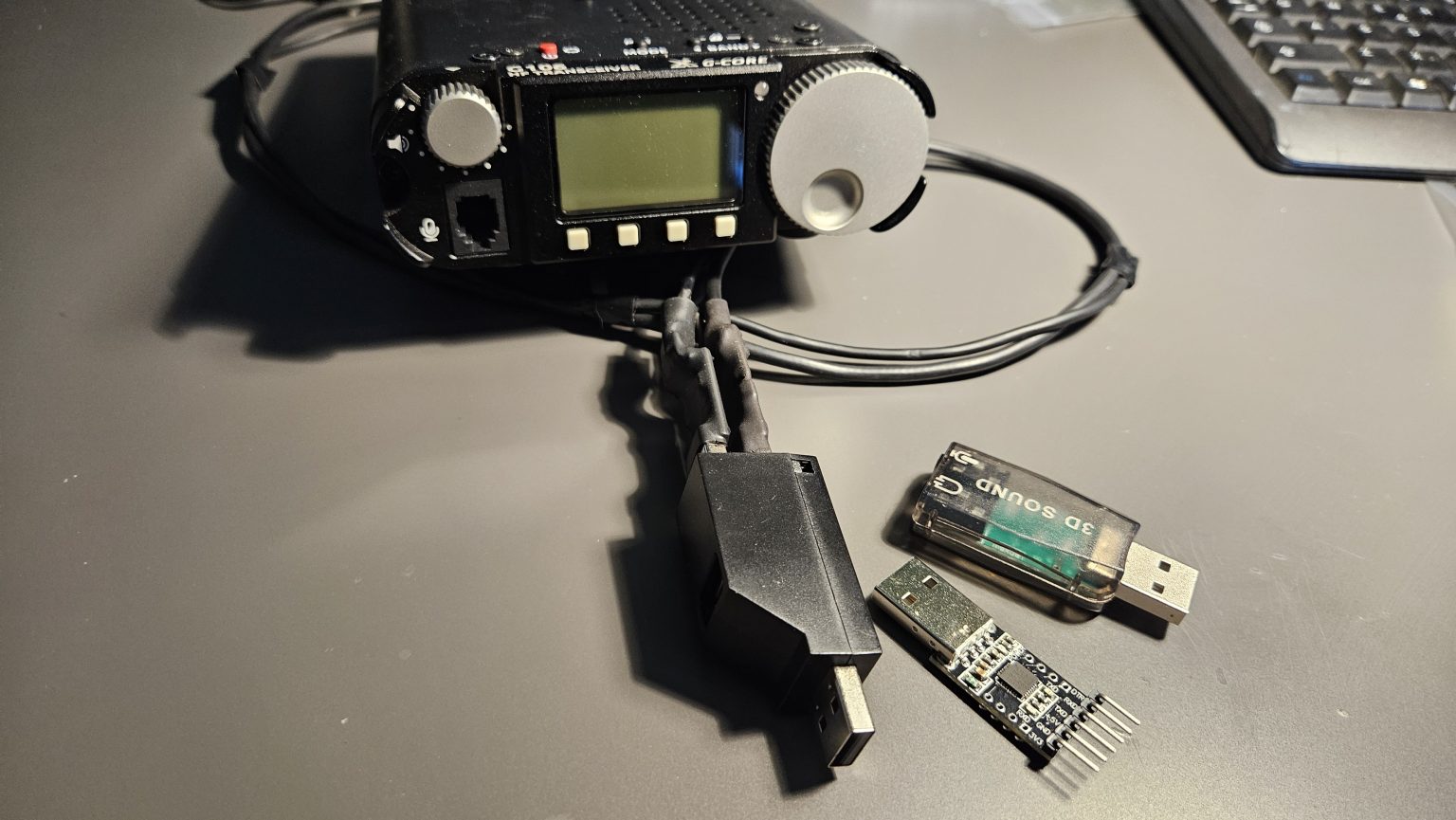
TTL and LVTTL serial
In microprocessor systems, for short connections, direct logic levels are used instead of the inverted high voltages of RS-232. TTL defines logic 0 as 0 V and logic 1 as 5 V, while LVTTL uses 3.3 V logic levels.
It is important to note that RS-232, TTL, and LVTTL electrical levels are not compatible, and connecting different technologies directly can damage devices. Level-shifting components (such as MAX232) are required.
RS-232 connectors
The original RS-232 standard used the DB-25 connector, later replaced in PCs by the 9-pin DE-9 (commonly called DB-9), which became the de facto standard.
DE-9 pinout (DB-9)
| Pin | Signal | Name | Direction |
| 1 | DCD | Data Carrier Detect | DCE → DTE |
| 2 | RXD | Receive Data | DCE → DTE |
| 3 | TXD | Transmit Data | DTE → DCE |
| 4 | DTR | Data Terminal Ready | DTE → DCE |
| 5 | GND | Signal ground | |
| 6 | DSR | Data Set Ready | DCE → DTE |
| 7 | RTS | Request To Send | DTE → DCE |
| 8 | CTS | Clear To Send | DCE → DTE |
| 9 | RI | Ring Indicator | DCE → DTE |
Flow control
Serial communication requires mechanisms to regulate data flow between transmitter and receiver.
XON/XOFF
Flow control can also be implemented in software using special control characters XON and XOFF. This method does not require additional hardware lines but uses bandwidth and may interfere with binary data.
Null modem cable
To connect two DTE devices directly, a null modem cable is required. A full version crosses all control lines, while a minimal version crosses only TX/RX and GND.
Troubleshooting
Serial communication is simple but requires precision. Most issues are caused by mismatched baud rates, incorrect framing, missing flow control, incompatible electrical levels, or incorrect cabling.
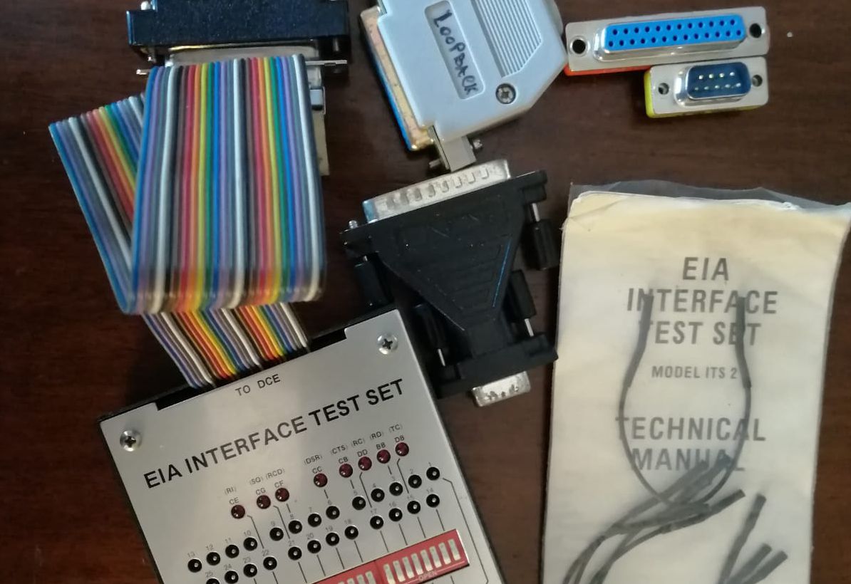
In the title image: RS-232 debugging is performed using a breakout box that allows monitoring and modifying signal lines in real time.
Post Comment