To truly understand the analog side of digital communications, it is essential to have a clear grasp of the three fundamental quantities involved when information is transferred through radio waves: amplitude, frequency, and phase.
The Circle Behind the Sine Wave
When trying to understand what amplitude, frequency, and phase really are, there is a mental image worth more than a thousand formulas. Not a mathematical expression, not an abstract graph, but a concrete scene: a point in motion.
Imagine a point moving along a circle at a constant speed. Nothing more: it is simply rotating, like the hand of a clock, without accelerating or slowing down.
Now take that scene and project the point onto the horizontal axis, as if a light were shining on it from above and you were watching its shadow move back and forth. If you plot that position over time, you obtain exactly a sine wave.
This connection is not a mathematical trick: it is the key to understanding what an oscillating signal really is. A sine wave is not an “invented” curve; it is the shadow of uniform circular motion. From this point on, many concepts in signal theory stop seeming abstract.
This image1 is particularly illustrative.
Amplitude, Frequency, and Phase Seen from the Circle
With this image in mind, the three fundamental parameters become immediately intuitive.
Amplitude is the radius of the circle. If the circle is large, the shadow oscillates widely; if it is small, the oscillation is limited. Increasing the amplitude of a signal literally means enlarging the circle.
Frequency is the speed at which the point rotates. If the point completes many revolutions per second, the oscillation is rapid; if it rotates slowly, the wave becomes more stretched out. Frequency is simply how fast the circle is traversed.
Phase is the least intuitive parameter, but with this image it becomes clear: it is the angle at which the motion begins. If two points rotate on the same circle at the same speed but start from different positions, their projections generate sine waves that are identical in shape but shifted in time. In the image, the blue line and the red line are 90 degrees out of phase.
Two signals with the same amplitude and frequency but different phase are like two runners on the same circular track, moving at the same speed but starting from different positions.
From the Circle to the Plane: The I/Q Representation
So far we have observed only one projection. However, the rotating point always has a complete position in the plane.
If we project the point onto the horizontal axis, we obtain a first signal called I (In-phase): the blue line. If we project it onto the vertical axis, we obtain a second signal called Q (Quadrature): the red line.
The two signals are automatically 90° out of phase because they are orthogonal projections of the same motion: this is not a design choice, but a geometric consequence.
At this point, the way we look at the signal changes. We no longer describe it merely as a waveform evolving over time, but as a point2 moving in a plane. At every instant, that point has a precise position:
- its distance from the origin represents the amplitude
- its angle relative to the horizontal axis represents the phase
- the speed at which it moves around the circle represents the frequency
The signal is therefore no longer just something that “oscillates”: it is something moving through space along a trajectory. In practice, from the behavior of the red and blue lines we derive the green point moving around the circle. I and Q are therefore not arbitrary signals: they are the coordinates of this point. Separately, they describe only a projection; together, they completely describe its motion3.
Why All This Is Essential in SDRs
In modern Software Defined Radio (SDR) systems, such as GNU Radio and the many physical SDR devices available today, the signal is not treated as a single quantity varying over time, but precisely as a pair of values: I and Q.
This is fundamental because a single real-valued signal does not allow phase to be measured in an absolute sense: a reference is required. The I/Q representation provides exactly that, anchoring the received signal to a local oscillator and making phase measurable. In modern modulation schemes, where information is encoded in phase—or in combinations of amplitude and phase—this capability becomes indispensable.
Working with I and Q also makes it possible to perform everything in software: frequency translation, filtering, demodulation, and analysis. It is this representation that makes an SDR extremely flexible.
Without I/Q, an SDR would be a limited receiver. With I/Q, it becomes a universal instrument.
The Direct Link to Modulation
As we will see, this way of looking at signals becomes immediately useful when discussing modulation.
In amplitude modulation (AM), what changes is the distance of the point from the origin: it varies over time following the modulating signal, while the direction remains constant.
In frequency modulation (FM), what changes is the speed at which the point moves around the circle.
In digital modulation schemes such as QPSK or QAM, the point does not move continuously but instead “jumps” between specific positions in the I/Q plane. Each position represents a particular combination of bits.
This is why constellation diagrams display discrete points instead of waveforms: we are directly observing the possible positions of the point in the plane.
A Change in Perspective
The connection between the circle and the sine wave is not merely a useful analogy: it is a change in perspective.
We move from a passive view of the signal—a curve that rises and falls—to a dynamic one: a point in motion, with a position, a speed, and a trajectory.
It is this perspective that makes SDRs, digital modulation schemes, and, more generally, the entire theory of signals easier to understand.
Once you begin to see that point, many things stop being complicated and start feeling natural.
 Info
Info1) The animation is by Lucas Vieira from Wikimedia Commons (released into the public domain).
2) Readers familiar with mathematics will recognize that the “point” we are discussing is actually a vector: an arrow starting at the origin of the axes and ending at the point itself. Describing the signal as a “moving point” and as a “rotating vector” are simply two ways of expressing the same idea: the point is merely the tip of the arrow. The vector representation is the one commonly used in technical literature, where the signal is written as a complex number in the form I + jQ—but this is a notation, not a different concept. The point rotating in the I/Q plane and the rotating vector are the same idea viewed from different perspectives.
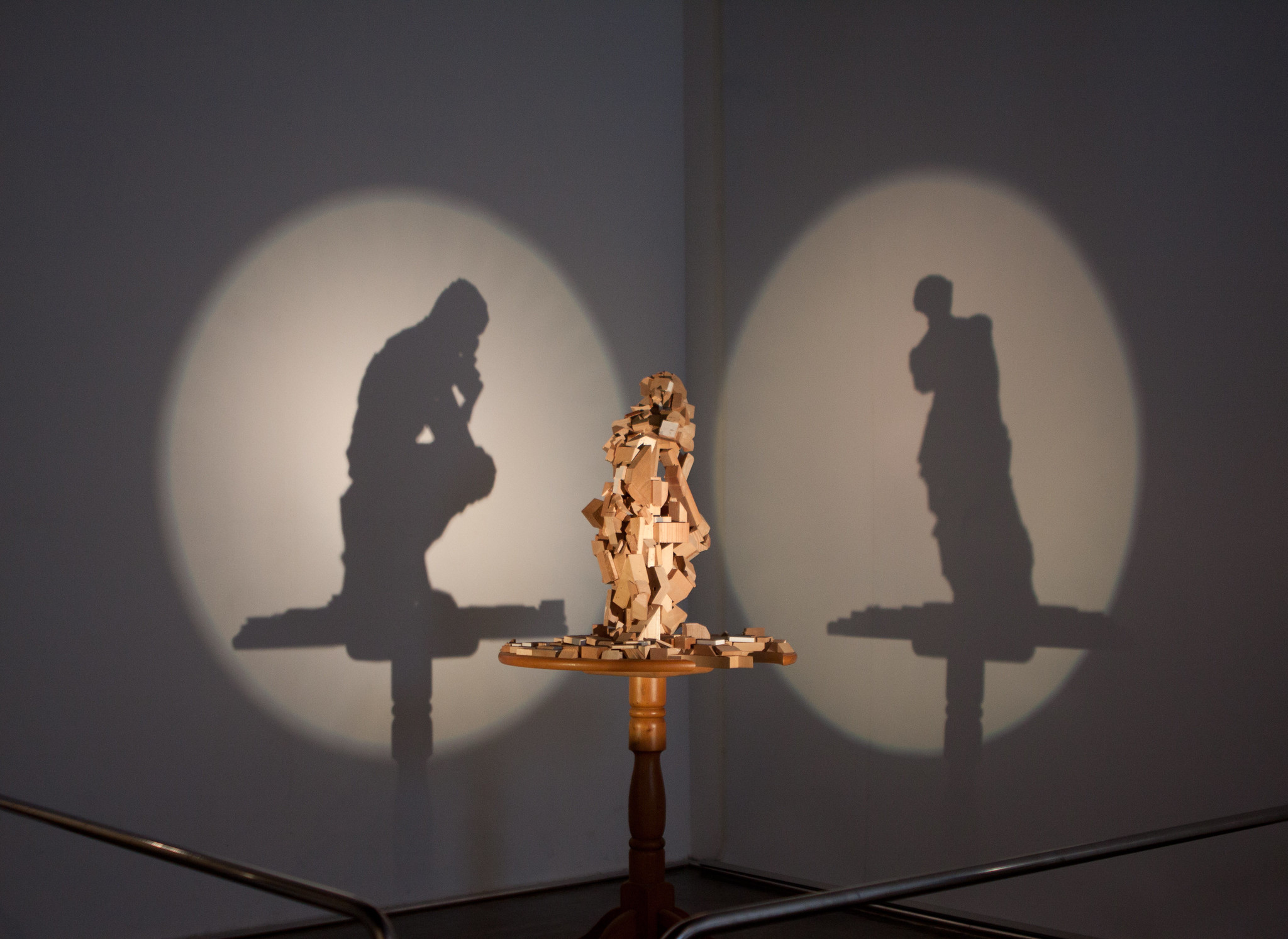
3) It is the same concept by which it is not always possible to reconstruct the shape of an object solely from its shadows. As illustrated by the title image, taken by jirka matousek of an exhibit at the Trick Eye Museum in Seoul (licensed under CC BY 2.0).