Modern equipment, except for rare cases, is all powered at 12V, so to operate from the mains it requires a power supply. In addition, since multiple low‑voltage devices are normally used in the shack1, it is also useful to think about a low‑voltage distribution line.
How to proceed? The nominal voltage of the devices is usually 13.5V, suitable for use in vehicles. In general, the acceptable voltage range is wider, but it is always good practice to check the device manual to know the allowed voltages. The specifications also indicate the current consumption, which is the other important element for properly sizing the power system. As a rule of thumb, QRP devices draw less than 5A, while 100W radios reach 20A. The power supply must provide the nominal voltage with a current equal to or greater than the maximum consumption of the device (or devices) being powered.
The choice of the right model must start from a few basic considerations.
Power supplies
Power supplies can be grouped into two major families.
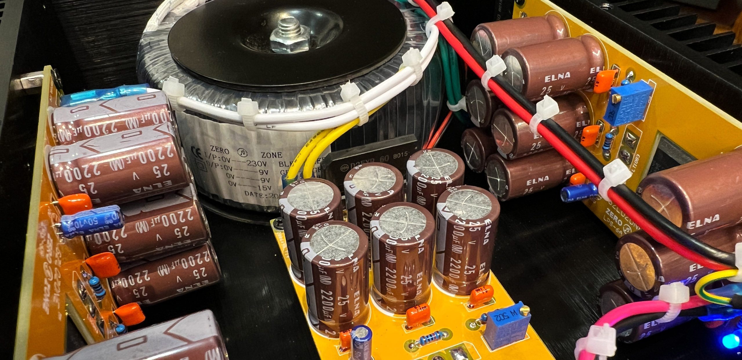
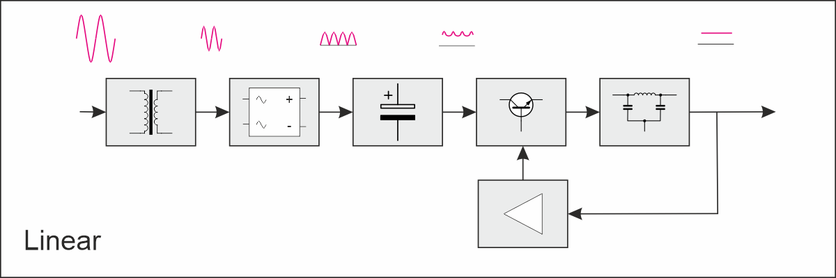
The first is that of linear power supplies. The mains voltage is reduced by a low‑frequency transformer (50 Hz in Europe) and brought to a voltage slightly higher than required. This AC voltage is first rectified and filtered, becoming DC but not stabilized. The regulation circuit operates through one or more transistors-or integrated circuits-that act as a sort of variable resistor, continuously and linearly adjusting their conductivity to keep the output voltage stable. If well designed, this type has low output impedance and virtually no noise. The downside lies in the size of the components, mainly the transformer and heat sinks, since the regulation dissipates as heat the energy contained in the difference between the unregulated voltage and the output voltage for the required current. This also affects the efficiency of the power supply, which is relatively low.
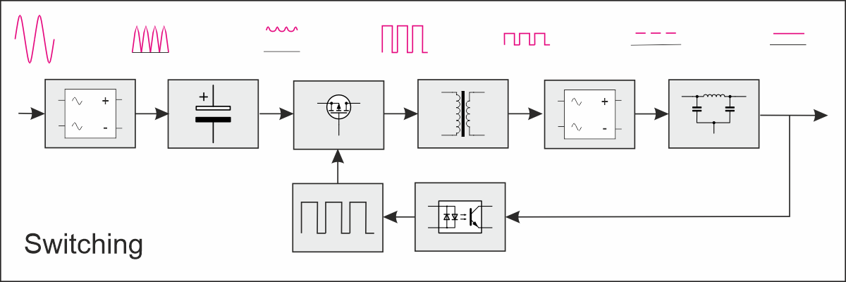
The second family is that of switching power supplies. In these, the mains voltage is rectified and filtered directly, and then switched at high frequency by one or more transistors driven by a square wave at tens or hundreds of kHz. A square wave can be thought of as two states: in the first (0) the transistor does not conduct, in the second (1) it conducts. The regulation circuit measures the output voltage and adjusts the ratio between the duration of the two states: the longer the “1” state, the higher the output voltage. This voltage is passed through a high‑frequency transformer, much smaller and lighter than a low‑frequency one, and then rectified and filtered. The advantages are high efficiency, reduced size and weight. The downside is that switching generates noise and harmonics which, if not properly filtered and suppressed, can cause interference both in radio frequencies and in audio.
In recent years the trend has clearly shifted toward switching power supplies, but in amateur radio use it is important to consider the RF noise generated by the power supply. If the EMI filters of switching supplies are well designed, problems are rare. If they are poorly designed-or even absent, as often happens with LED power supplies-the power supply behaves like a broadband noise source, and the power cable like an antenna. Consider that an ideal square wave has an infinite series of harmonics; in reality, rise and fall times are never instantaneous, which limits the effective bandwidth, but a poorly built switching supply can create dramatic effects and make some bands-especially the lower ones-completely unusable.
The noise level of a power supply is easy to check, even with a simple AM radio.
For some services that handle very weak signals, such as antenna preamplifiers, it is advisable to avoid switching power supplies altogether-given the low currents involved-and prefer linear supplies with excellent filtering.
Connectors
While nothing prevents you from connecting devices directly to the power source without connectors, my suggestion is to avoid this approach and always use polarized connectors. This is not a whim: it is a matter of reliability, safety, and operational continuity.
The first goal is to avoid polarity reversal, an error that is the most common cause of equipment failure. If the device is not protected-and not all devices are-you risk seriously damaging valuable equipment. With a non‑polarized connector (single fastons, banana plugs, loose terminals, improvised jacks), it is simply too easy to make a mistake in a moment of haste, darkness, rain, contest, field day, etc. Mechanical polarization ensures that an incorrect insertion is physically impossible.
The second goal is to reduce errors, which are always possible when in a hurry or when multiple people handle the same equipment. In amateur radio, work is often done in civil protection groups, contests, field days, expeditions, shared installations. With polarized connectors, you can operate without worrying.
The third goal is compatibility between different devices: rarely does the power cable of one device fit another, but if you use the same polarized connectors, you can connect any device to any power source safely.
This is why in radio it has always been essential to use polarized connectors for all power lines, especially those above 5–10 A. Human error is inevitable, so the connector must physically prevent the mistake. You don’t need an expert “being careful”: you need a system that does not allow mistakes. XT60, Powerpole, Anderson SB, Molex Mini‑Fit, etc.-anything polarized is a major improvement over improvised solutions.
Powerpole
In the amateur world, the Anderson PP15/30/45 Powerpole connector has become very popular.
Today it has become almost a de facto standard for 12–13.8 V DC. It has many advantages:
- Polarity cannot be reversed if assembled correctly.
- No risk of short circuit when the connector is exposed.
- Handles high current (30–45 A without issues).
- Quick connection, excellent for mobile, contests, field days, fast setups.
- Widely available, inexpensive, robust components.
- It is a hermaphroditic connector: the same piece works as plug and socket.
Personally, I don’t like it very much, mainly because of its size, so for my low‑voltage distribution ecosystem I use XT60 connectors.
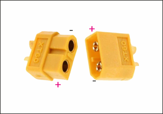
- Small and lightweight, very compact.
- Rated for 60 A continuous, but in practice they handle 30–40 A without heating.
- Perfect for high‑power HF radios, amplifiers, LiFePO₄ batteries, inverters, etc.
- Gold‑plated contacts and a very “straight” insertion reduce resistance and voltage drop compared to DC jacks and often even Powerpoles.
- Solid mechanical coupling: once connected, they NEVER disconnect accidentally.
- Highly appreciated in field days, SOTA, POTA, contests, and real mobile setups.
Since you may need to interface with the outside world, I always keep Powerpole‑to‑XT60 adapters in my bag, ensuring easy interoperability. It’s a setup that gives me the best of both worlds.
And when I can’t use them?
There are situations where you cannot use your preferred connector. For example, when you must connect with clamps to a car battery, or when using a power supply with classic binding posts. But even in these cases, a bit of foresight is enough to avoid disasters.
I use a very simple solution, which more than once has helped me avoid serious mistakes.
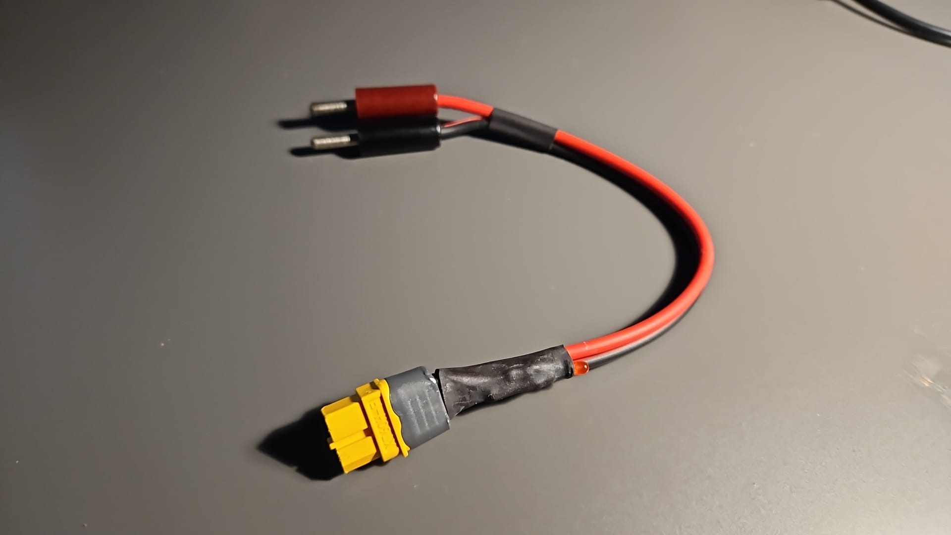
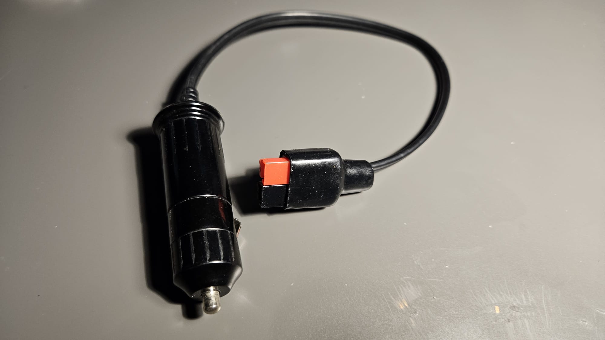
In adapters that end with non‑polarized solutions-such as banana plugs in the photo-I use a status LED that indicates when the polarity is correct. If it is on, the polarity is correct and voltage is present. If it is off, something is wrong: check before connecting anything else.
More information here.
The cable
Lastly-but certainly not least-comes the choice of cable. QRP devices operate with relatively low currents, but 100‑Watt transceivers reach and exceed 20A, which is significant. Cables must therefore be properly sized. A rule of thumb suggests using a cross‑section of 1 mm2 for every 4 A of current draw.
But rather than approximations, it is better to rely on more rational calculations, since one important factor must be considered: length. To simplify things, I created a simple calculator that suggests the appropriate commercial cable size based on the parameters entered.
For cables as well, it is always good practice to use wires that allow immediate visual identification of polarity: specifically, the classic red (positive) and black (negative) cable.
 Info
InfoImage credit: Chepry, from wikimedia commons