
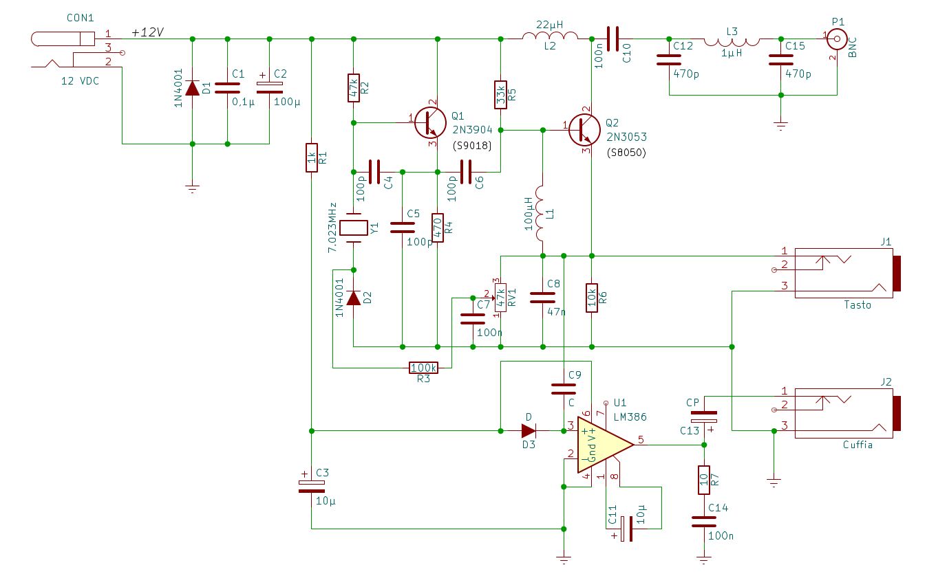
Analysing the Pixie schematic
With the theoretical foundations acquired, we can finally begin to analyse the Pixie circuit diagram, block by block.
The power supply
Every “active” device needs energy to operate, and electronic circuits are always designed to work within specific voltage limits. The Pixie is designed to operate between 9 and 12 Volts DC, typically supplied by a battery. The stability (and quality) of the power supply is an important factor in the operation of any electronic circuit: variations or noise on the supply line can easily affect the generated signal.
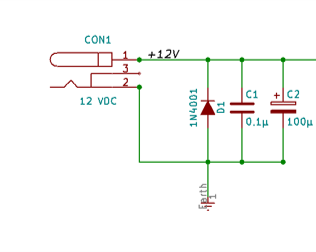
The Pixie’s power supply stage consists of only four components:
- D1 is a 1N4001 diode;
- C1 is a 100 nF ceramic capacitor;
- C2 is a 100 µF electrolytic capacitor.
The function of diode D1
In this position in the circuit, diode D1 has a protection function. If the power supply polarity were accidentally reversed, the polarized components downstream (especially semiconductors) could be damaged or destroyed.
With the power supply connected correctly, D1 is inactive: current flows through the circuit normally and the diode, being reverse biased, does not conduct. If the power supply is connected with reversed polarity, however, D1 conducts, short-circuiting the supply line — thus protecting the rest of the circuit, at the cost (typically) of blowing a fuse or causing the power supply to enter current limiting mode. This is much less expensive to replace than a burned transistor. It is always good practice to include a fuse in the power supply line of an electronic circuit, sized to interrupt the supply if the current significantly exceeds its normal value.
The oscillator: the “heart” of the Pixie
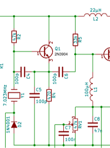
The oscillator is, quite literally, the heart of the Pixie: it generates a sine wave signal at the operating frequency of the transceiver. This generation must be as frequency stable as possible: a requirement that is far from trivial, as we will see. The active element of the oscillator is transistor Q1.
An oscillator, in general, is simply an amplifier in which part of the output signal is “fed back” to the input (positive feedback). An oscillator does not “create” a signal from nothing: it uses the energy supplied by the DC power source and converts it into a periodic signal at a well-defined frequency. The three most common circuit configurations used to build oscillators are: Hartley, Colpitts and Pierce. The Pixie uses a Colpitts oscillator stabilized by a quartz crystal.
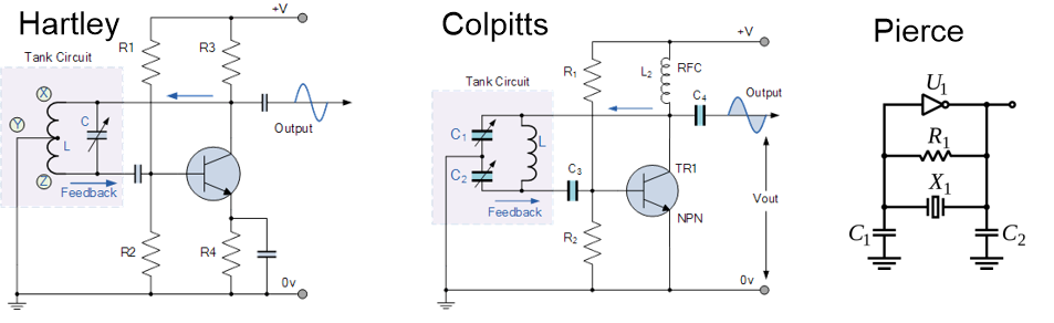
Why is an LC circuit not enough?
To determine the operating frequency of an oscillator, a reference mechanism is required. The simplest method, conceptually, is to use a tuned circuit: the combination of a capacitor (C) and an inductor (L), hence the name LC circuit.

By correctly sizing L and C, it is possible to determine the resonance frequency of the circuit with good accuracy. The problem is that an LC circuit built with discrete components is not sufficiently stable to reliably drive a CW transmitter: it is affected by parasitic elements (the unwanted capacitances and inductances we have already discussed), and the components themselves are sensitive to operating temperature, which causes their values to change slightly. As a stable reference source, the Pixie therefore uses a quartz crystal.
The quartz crystal
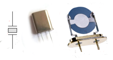
Quartz crystals exploit the piezoelectric properties of certain materials to stabilize an oscillator. A precisely cut quartz wafer is the most commonly used element: its mechanical characteristics (dimensions and cut) determine the resonance frequency with great accuracy. Today, ceramic materials with similar characteristics to quartz are also used, as they are less expensive. Quartz crystal oscillators (XO) are stable enough for most amateur radio applications; for applications requiring greater precision, they can be further temperature stabilized (the so-called TCXO, Temperature Compensated Crystal Oscillators). We can imagine a quartz crystal as a microscopic tuning fork: when properly excited, it tends to oscillate at its own natural frequency, imposing it on the entire oscillator.
In this circuit, the quartz crystal becomes the element that determines the oscillation frequency with extreme precision, performing the role that in other oscillators is assigned to a tuned LC circuit.
The Pixie “RIT”
One of the most ingenious (and most economical) aspects of the design is how the fine frequency adjustment during reception is achieved, the so-called RIT (Receiver Incremental Tuning).
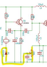
The Pixie does not use a mechanical variable capacitor, but instead exploits an electrical property of diodes: reverse-biased diodes exhibit a small variation in capacitance proportional to the applied bias voltage. There is a family of diodes specifically designed for this purpose, called varicap (or varactor) diodes; in the Pixie, however, to reduce costs, a common 1N4001 diode is used instead (the same type used for protection D1). Its behaviour as a varicap is very modest, but sufficient for the purpose.
The adjustment line (controlled by trimmer RV1) is active only during reception: when the Morse key is pressed, diode D2 is no longer biased, and the frequency automatically returns to the base value determined by the quartz crystal. In this way, it is possible to slightly shift the listening frequency to better centre the signal of the corresponding station, without changing the actual transmit frequency, which remains firmly anchored and stable to the crystal.
Seeing it with your own eyes
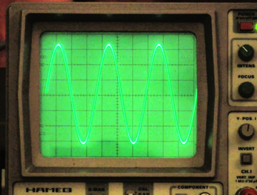
By connecting an oscilloscope to the emitter of Q1, it is possible to directly observe the waveform generated by the oscillator: it is, to a good approximation, a sine wave. Even without an oscilloscope, tuning a nearby receiver will allow you to hear the circuit’s emission as a continuous tone.
However, one question remains: how can a simple continuous “tone” allow us to receive radio signals? The answer will be in the next chapter.