Direct conversion
In the previous page we left with a question: how can a simple sine wave generated by the oscillator allow us to receive radio signals? The answer lies in the principle of direct conversion.
Direct conversion
When two signals are applied to a non-linear device, several mixing products are generated, including two fundamental components: the sum and the difference of the original frequencies.
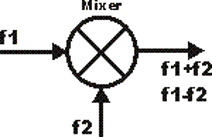
In a direct conversion receiver, the signal captured by the antenna is mixed with the signal coming from the local oscillator (in our case, the quartz crystal oscillator we have just analysed). If the two frequencies are very close to each other (as happens when the local oscillator is close to the frequency of a signal in the band), the “difference” signal falls within the audible frequency range: a few hundred Hertz, which are reproduced as a tone in the speaker or headphones.
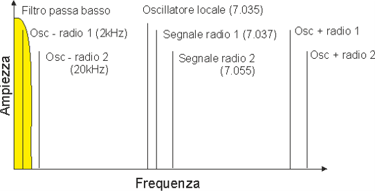
At the output of this stage, called the mixer, it is therefore sufficient to have a filter that rejects the sum signal (which falls in the radio frequency range, twice the operating frequency) and allows the difference signal (the audio component) to pass through, in order to obtain the received signal audio directly.
The Pixie mixer
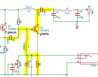
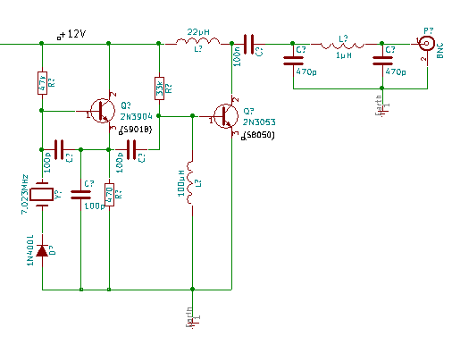
In the Pixie, mixing is performed by the same transistor that acts as the power amplifier during transmission: Q2. This is one of the most elegant (and economical) aspects of the design:
- the signal generated by the oscillator is injected into the base of Q2 through capacitor C6;
- the signal captured by the antenna enters instead through the collector, via C10;
- the result of the mixing between the two signals is available across C8/R6, from where it is taken and sent to the audio amplifier;
- L2 is simply a blocking choke: it allows the DC current needed to power Q2 to pass, while preventing the RF signal from reaching the power supply.
It should honestly be noted that in the Pixie there is no real low-pass filter made with dedicated passive components after the mixer: the “filtering” of the sum product is largely entrusted to the frequency response of the following stages. This is one of the typical compromises of such an essential design, and it helps explain why the Pixie’s reception performance, while functional, is not particularly outstanding.
What happens during transmission?
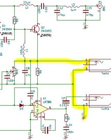
Pressing the Morse key grounds a circuit line, triggering a chain reaction:
- the voltage across trimmer RV1 goes to zero;
- this changes the bias conditions applied to transistor Q2, switching from those suitable for weak-signal mixing to those suitable for delivering power;
- at the same time, pressing the key grounds the line carrying the audio signal towards the amplifier IC, muting it during transmission (preventing annoying hum or feedback in the headphones).
With the simple press of a key, therefore, the same circuit stage completely changes its behaviour: from a receiver mixer it becomes a transmitter power amplifier. This is a very instructive example of how, by changing the bias conditions (that is, the operating conditions) of a component, the same physical elements can perform radically different functions.
The “transmitter” and the P.A.
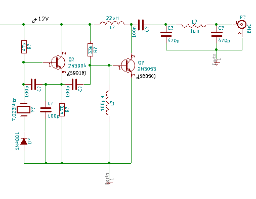
During transmission, Q2 therefore becomes the final power stage (P.A., Power Amplifier): it amplifies the signal present at the base and delivers it to the output through the collector. The two inductors present in this part of the circuit are used to correctly bias the transistor. The output signal, in the order of a few hundred milliwatts (typically between 300 and 800 mW, depending on supply voltage and the actual transistors installed), is sent towards the antenna through a 100 nF coupling capacitor.
Harmonics and intermodulation
A pure sine wave is, from a spectral point of view, a spectrally pure signal: it contains energy at a single frequency. Any distortion of a real signal causes the generation of harmonics: unwanted components at integer multiples of the fundamental frequency.
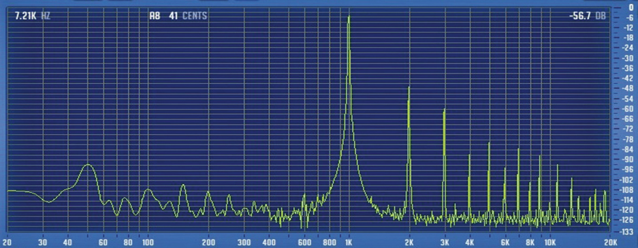
Producing a perfectly sinusoidal signal and building perfectly linear amplification circuits is, in reality, completely impossible: practically every real electronic system contains some harmonic content, even if minimal. A related but distinct phenomenon is intermodulation: when multiple signals pass together through devices that are not perfectly linear, additional unwanted signals are generated, resulting from combinations of the original frequencies.
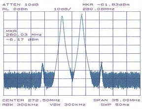
Intermodulation has particularly negative effects in receivers (where it can generate false signals or interference), but it must also be minimized in transmitters, exactly as with harmonics: a spectrally dirty transmitter can interfere with other users of the radio spectrum far away from its own operating frequency.
The pi filter
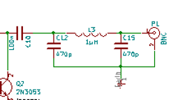
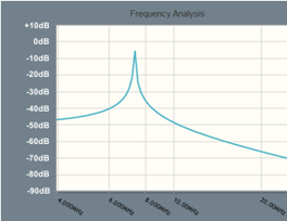
In the Pixie, unwanted output signals are limited by a pi filter (named after the shape of its schematic, which resembles the Greek letter π): a network made of inductors and capacitors that performs two fundamental functions: it matches the impedance of the final amplifier stage to that of the antenna and attenuates the harmonics generated by the non-linear operation of the transistor. The following image shows the theoretical response of the filter implemented in the Pixie.
A note about decibels
The attenuation (or gain) of a filter, or more generally of an electronic stage, is measured in decibels (dB). The decibel is not actually an absolute unit of measurement, but expresses a ratio between two quantities, measured on a logarithmic scale. Some useful reference values to remember:
- +3 dB corresponds to doubling a power value;
- +6 dB corresponds to doubling a voltage value (with the same impedance);
- According to the IARU convention for reception measurements, on signal strength meters (S-meters), each S point conventionally corresponds to 6 dB, with S9 in the HF bands defined as 50 µV.
These references will be useful whenever we discuss the performance of filters, amplifiers or antennas.
Audio amplification
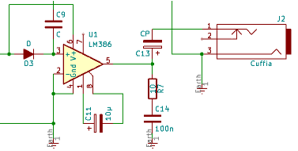
The amplification of the weak audio signal coming from the mixer is entrusted to a very common dedicated integrated circuit: the LM386. The components surrounding the IC are those recommended in the manufacturer’s application notes. The value of capacitor C11, connected between pins 1 and 8, controls the amplifier gain: without this capacitor the gain is approximately 8 times, while with this capacitor (as in the Pixie) it rises to about 200 times, at the cost, however, of increased sensitivity to noise and the possibility of oscillations.
Even in this stage there is no dedicated low-pass filter, nor a volume control: the final “filtering” is simply entrusted to the frequency response of the final transducer used (headphones or speaker), which naturally attenuates the extreme frequencies.