Z-match
The Z-Match is an antenna tuner known for its simple construction and for the efficiency with which it can adapt a wide range of impedances, making it possible to use antennas that are not perfectly resonant without significantly affecting transmission. Its architecture is based on a circuit with coupled inductors and variable capacitors that work together to quickly reach the tuning point. It is a completely manual system, free of active components: for this reason it is robust, reliable and highly appreciated by radio enthusiasts who prefer practical and lightweight solutions.
In the QRP environment, where every watt has significant value, the Z-Match proves particularly suitable because it minimizes losses and makes the best possible use of the available power. Its compactness makes it ideal for portable activities such as hiking, park operations or mountaintop activations, and in general for anyone who wants to travel light without giving up the ability to tune improvised antennas. It also fits naturally in mobile use: the small size and ease of adjustment make it perfect for car installations or situations where the antenna cannot be optimized. In these scenarios, the speed with which it allows switching from one band to another and its ability to adapt to temporary configurations offer a concrete advantage.
In a fixed station, although originally designed as a lightweight and portable tuner, the Z-Match still finds valuable use. In this context it becomes a reliable manual tuner that allows the management of non-resonant antennas without resorting to more complex automatic systems. Its ability to cover a wide impedance range makes it useful for multiband antennas or long wires, which are often difficult to match with other types of tuners.
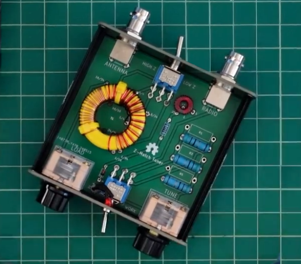
Last but not least, the Z-Match can be easily homebrewed, as it does not require particularly critical components, although today many industrial products are available on the market, often at prices lower than the total cost of the individual components.
The schematic
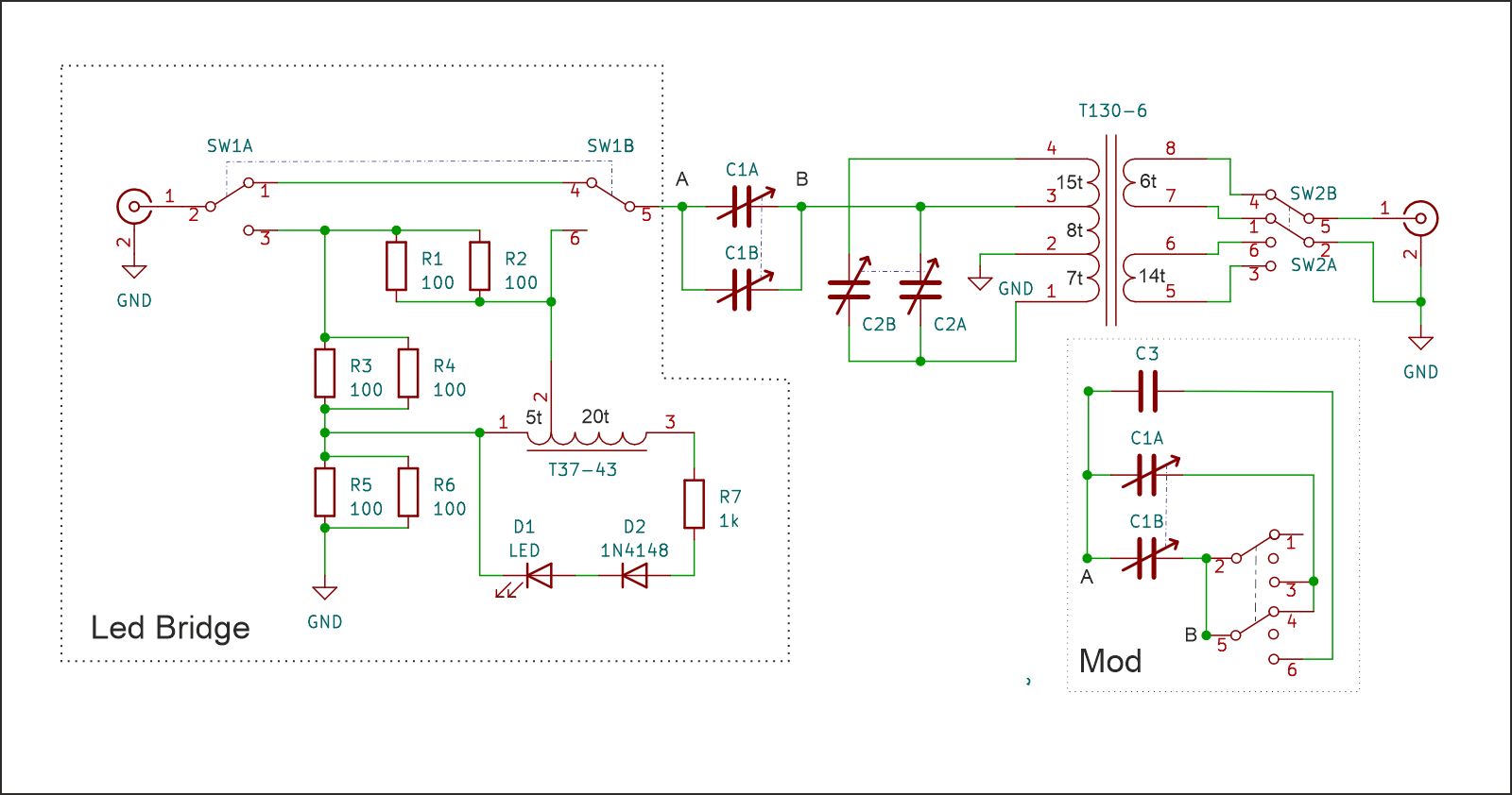
The Z-Match is a tuner based on a fixed-inductance resonant circuit that uses variable coupling through two capacitors to achieve impedance matching toward both balanced and unbalanced loads. Unlike T or π tuners, the heart of the circuit is a resonant transformer that acts as a combined system: variable transformer + band-pass filter.
The design originates from the classic schematic published in SPRAT No. 84 by the G-QRP Club magazine, later modified by W6JJZ and paired with an LED SWR bridge based on the design by Dan Tayloe, N7VE.
The SWR bridge
The SWR indicator is the first stage of the project and is essentially a modified Wheatstone bridge, built with two non-inductive 100 Ω / 1 W resistors in parallel on the reference arm (yielding 50 Ω), a divider for forward and reflected detection, and a LED as an indicator of reflected power imbalance.
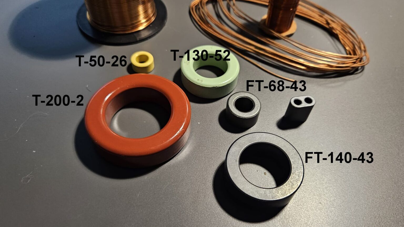
The transformer driving the LED is wound on a T37-43 toroid with 25 turns of enameled wire and a tap at the fifth turn.
Capacitive section
The second stage consists of the capacitive section, made with a 365+365 pF variable capacitor with its two sections coupled. Commercial versions generally follow the original schematic, but a modification can be added using a three-position switch (center-off) that allows a more flexible configuration:
- one single section of the variable capacitor (for higher frequencies);
- the two sections in parallel;
- the two sections in parallel with a fixed 470 pF capacitor, improving efficiency on the lower bands.
The modifications are shown in the schematic at points A–B.
Main transformer
This is followed by the main transformer, wound on a T130-6 toroid (or T200-6 for higher power). The primary consists of 30 turns of enamelled wire, with taps at the seventh and fifteenth turns. The transformer has two secondary windings, one for low-impedance antennas and one for high-impedance antennas, selectable via a two-section switch. The secondaries are wound over the primary windings to improve coupling. One consists of six turns, the other of fourteen.
Operation
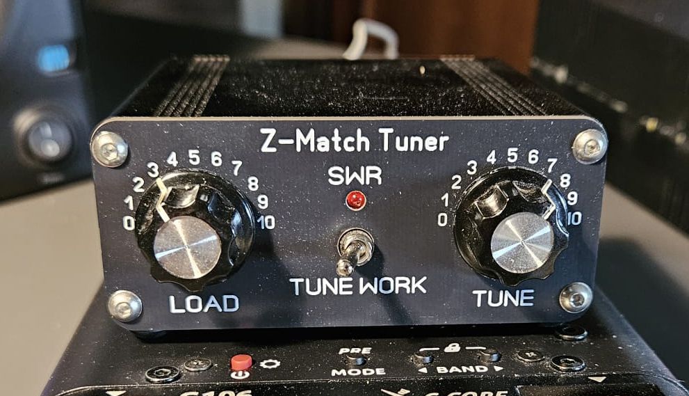
Operation is very simple: just enable the LED bridge via switch SW1 and tune C1 and C2 until the LED reaches minimum brightness. Once the minimum is found, set SW1 back to the bypass position and you are ready to operate.
This configuration is perfect for QRP mobile use, where low power levels often make it difficult to obtain reliable readings with traditional SWR meters. The LED bridge indication is accurate even at very low power.
As for the other components, the voltages involved do not require particular specifications. Today variable capacitors are somewhat harder to find, but the entire circuit remains simple, reliable and convenient, especially because it can directly handle balanced antennas without the need for an external balun.
The only trade-off is a rather narrow tuning window, with sharp peaks and some sensitivity to small movements of the variable capacitors (usually not reduction-geared). With a bit of experience, excellent results can be achieved, with low cost and very small size.
As mentioned, the Z-Match can be easily home-built, but it is also available in numerous commercial versions, often mass-produced in China and based on classic radio amateur designs.
Post Comment