When you go above 30MHz and move into VHF, UHF and SHF, antennas become precision instruments. Dimensions shrink dramatically: at 144 MHz a half-wave dipole is about 1 meter long, at 432 MHz it drops to 35 cm, at 1.2 GHz we’re at 12 cm. This allows for more complex geometries, higher gains and highly controlled patterns, and makes wire antennas less practical.
Vertical antennas are the most common, with 360° coverage and moderate but very useful gain, widely used for local traffic. A classic VHF ground plane offers typical gain of 4-5 dBi (1), with a fairly wide lobe and low radiation angle, ideal for terrestrial links. Even above 30 MHz, multiband verticals (like 144/430 MHz) are common.
A special type of vertical is the collinear: by stacking sections in phase, the vertical lobe flattens and gain increases. A good collinear for 144/430 MHz can achieve 6–9 dBi, with a vertical beamwidth of just a few degrees. It’s the perfect antenna for combining decent gain without needing a rotator to point the antenna.
Yagis are similar to those used on HF, but with reduced dimensions, they become true directional tools on VHF and UHF. A 3-element Yagi for 144 MHz already delivers 9-10 dBi of gain, while a 9-element can exceed 13 dBi. On UHF, the numbers grow even more: a 15-element for 432 MHz can reach 14–16 dBi.
As gain increases, the beam narrows: a contest-grade Yagi (16-18 dBi) may have a beamwidth of 15–25°. It’s the ideal antenna for DX, contests, EME.
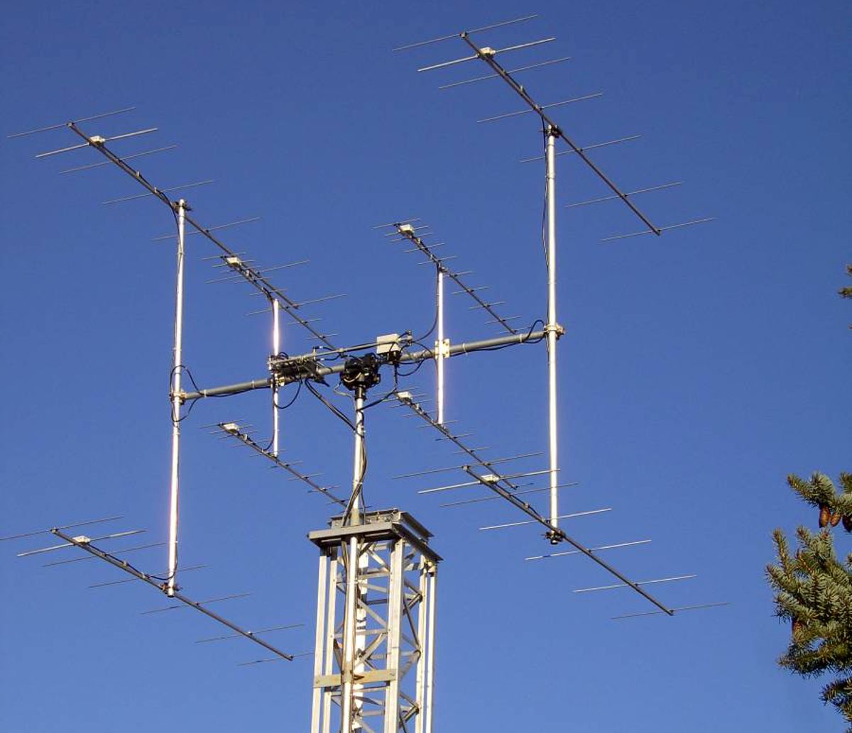
For satellite operation, where polarization becomes critical, Yagis can be mounted in cross-polarization: two identical antennas mounted on the same boom, one horizontally polarized and one vertically polarized, with elements arranged at 90° to each other. This configuration allows you to select the best polarization in real time, combine signals to achieve circular polarization, compensate for satellite attitude variations, and drastically reduce losses due to polarization mismatch – which in theory can completely nullify the signal. By feeding the two Yagis with a 90° phase shift line, you obtain circular polarization (right or left depending on the phase). Feeding just one maintains linear polarization. By combining them with a switch, you can choose the most effective configuration during the satellite pass.
The same applies to quads: a single-element quad on VHF has gain slightly higher than a dipole, but with a cleaner pattern and lower noise. A 4-element for 144 MHz can achieve 10–11 dBi, with a beamwidth similar to that of an equivalent Yagi.
Log-periodic antennas on VHF/UHF are wideband antennas par excellence. They often cover from VHF through SHF in a single structure. While gain is more modest compared to a Yagi – typically 6–8 dBi – the advantage is that it’s constant across the entire band.
They are perfect for monitoring, measurements, professional services, and for those who want a directional “universal” antenna.
The discone is an ultra-wideband antenna, typically used for reception. A good discone covers from VHF through SHF, with stable and acceptable impedance. Gain is near zero (0–2 dBi), but the bandwidth is truly extensive.
It’s ideal for aircraft monitoring, services, PMR, amateur radio for continuous monitoring.
Another specialized receiving antenna is the QFH (Quadrifilar Helix). It’s an antenna designed to cover the sky, with stable circular polarization and an omnidirectional pattern. Its structure consists of two bifilar helices wound around the same support, with slightly different lengths and pitches. This geometry generates either right-hand or left-hand circular polarization, essential for tracking satellites without using rotators, as its main lobe is directed toward the zenith.
Antennas for SHF
Starting from the upper part of UHF, dimensions allow for effective use of other antenna types.
On SHF, the parabolic dish is the absolute queen: it consists of a parabolic reflector with a large surface area, which concentrates radio waves at a precise point – the focus – where the receiving antenna is located, often contained in a module called a Low Noise Block (LNB), or the transceiver antenna.
Larger dishes are made with a mesh reflector, using metallic mesh, so they can reflect microwaves while significantly reducing wind loading. This works when the mesh size is significantly smaller than the wavelength. In practice, it’s more common below 3GHz; for higher frequencies, continuous metal surfaces are often more practical as reflectors, if dimensions allow.
There are essentially two types of parabolic dishes: prime focus and offset.
Prime focus dishes consist of a symmetrical parabolic disk with the feed positioned at the center, suspended in front of the reflector. It’s the most intuitive solution and the easiest to design. The feed “sees” the entire surface, but blocks a small portion of the reflector; the illumination angle is wide (typically 60–70°), and they are best suited for amateur radio use. Gain depends on diameter and frequency. To give an idea, a 60 cm dish at 2.4 GHz typically exceeds 25 dBi of gain, a 1m dish at 10GHz exceeds 30 dBi.
It’s the ideal antenna for point-to-point links typical of microwave activity.
The offset dish was born for the TV-SAT world, but has also become valuable for amateur radio operators. It is essentially a slice of a larger parabola, cut so that the focus is not in front of the center, as with prime focus, but outside the beam path. This means the feed does not obstruct the reflector at all, but the actual pointing angle is tilted relative to the dish, which can be mounted vertically even when the actual aiming direction is upward – making aiming more complex.
It’s the ideal choice for geostationary satellites such as QO-100 Es’Hail.
For both types, as with all directional antennas, beamwidth is inversely proportional to gain, and can therefore be very narrow: a few degrees for a 1-meter dish, around one degree for large dishes.
One of the most common in amateur circles is the horn antenna, one of the cleanest and most linear solutions for working in microwaves. It is, in practice, a waveguide that gradually widens – like a megaphone – allowing the electromagnetic wave to exit into free space without abrupt discontinuities. Its shape can be pyramidal, conical or sectoral, but the principle remains the same: the progressive widening of the waveguide transforms the energy confined in the guide into an orderly, clean beam with very low side lobes. It is this smooth transition between guide and free space that makes the horn so highly regarded in microwaves, where every geometric detail matters.
From a performance standpoint, a well-designed horn offers gain ranging from about ten to over 20 dBi, with a main beam that remains stable and predictable. It’s not an “extreme” antenna like a dish, but it is extremely linear: what you calculate is what you get, and this makes it valuable both as a standalone antenna and as a feed for prime focus or offset reflectors. In this latter role, it is practically irreplaceable, because it illuminates the dish uniformly and controllably, reducing side lobes and maximizing system efficiency.
For amateur radio operators working on 10 GHz and beyond, the horn is a faithful companion: robust, predictable, immune to the deformations that would ruin a Yagi or a patch. It has no thin elements to align, does not suffer from wind, and requires no complex tuning. It is an antenna that works because it is pure geometry, without compromises.
To work satellites on SHF, you can use the helix, a helical antenna designed to inherently generate circular polarization. It consists of a conductor wound into a spiral around a cylindrical support, with constant pitch and diameter. Polarization (RHCP or LHCP) simply depends on the winding direction. It typically operates in axial mode, meaning it radiates along the axis of the spiral. In this configuration, gain increases with the number of turns: a short helix (3–4 turns) has a wide beam and gain around 8–10 dBi, while a longer helix (8–12 turns) can exceed 15 dBi with a narrower beam. Bandwidth is relatively wide, often 10–15% of the center frequency, making it suitable for satellite systems and digital links. Construction is simple and tolerates small inaccuracies well, resulting in stable and repeatable performance even in non-ideal environments.
For completeness, a note on microstrip patch antennas: antennas with dimensions so small that they can be implemented directly on a printed circuit board. A patch is essentially a small metal plate suspended above a ground plane, separated by a dielectric. The most common shape is rectangular, but circular, triangular and complex geometries exist for specific requirements. Their strength is controllable polarization: with a single feed you get linear polarization, while with two feed points shifted by 90° you get circular polarization, a feature very useful for satellite applications and for feeding small dishes. Circular polarization is stable and repeatable, as it depends only on geometry and feed phase. From a performance perspective, a typical patch offers gain between 6 and 9 dBi, with a relatively wide beam (30–80° depending on size and frequency). Bandwidth is not huge – typically on the order of 2–5%.
Patches are widely used as feeds for offset dishes and for systems like QO‑100, where a well-designed circular patch illuminates the reflector uniformly and with correct polarization.
 Info
Info1) Gain expressed in dBi is relative to the isotropic dipole (more precisely, isotropic antenna), an ideal entity – which does not physically exist – used as a theoretical reference. It radiates uniformly in all directions of three-dimensional space, forming a perfect sphere; it has a defined gain of 0 dBi, meaning no preferential distribution of energy; it has no dimensions – it is a perfect radiating point – and is used as a comparison standard to evaluate the real gain of physical antennas.
A real dipole does not have a spherical radiation pattern – it has a donut shape – and in reality its gain typically ranges around 2 dB. This can also be used as a gain reference, denoted as dBd, with 0 dBd = 2.15 dBi.
Title image by Charly Whisky from Wikimedia commons