Bands and spectrum: the ham’s “territory”
Amateur radio activities take place in spectrum portions assigned by the ITU Radio Regulations and, in Italy, managed by the Ministry of Enterprises and Made in Italy (MIMIT).
These bands, ranging from long waves to microwaves, are assigned to the Amateur Radio Service with two different statuses:
- Primary, when the band is reserved with priority for radio amateurs (for example 7 MHz, 14 MHz, 144–146 MHz, 430–440 MHz);
- Secondary, when they must coexist with other services, operating cautiously and without interfering (as happens with 3.5 MHz, 10 MHz or some portions of 50 MHz and microwaves).
Each band has its own “personality”: some carry far with just a few tens of watts, others allow direct line-of-sight connections, still others open only under certain atmospheric or solar conditions.
Between 3.5 MHz and 430 MHz extends the heart of amateur radio activity, where tradition and experimentation coexist.
3.5 MHz Band (80 meters)
Status: secondary in Italy.
Characteristics: the “nighttime” band par excellence, shortwave (HF). 80 m waves propagate almost exclusively by ionospheric reflection during evening and nighttime hours, offering excellent medium-distance connections (300–1000 km). It’s the preferred band for local and regional QSOs, for national traffic and for CW and SSB activity.
Noisy and sensitive to atmospheric conditions, but fascinating for its vitality.
5 MHz Band (60 meters)
Status: the 5351.5–5366.5 kHz portion is allocated to the amateur service on a secondary basis; in Italy usage is subject to power limitations and technical conditions (typical limit: 15 W EIRP).
Characteristics: It’s a very interesting band because it’s located in a transition area that allows stable medium-distance communications all day long.
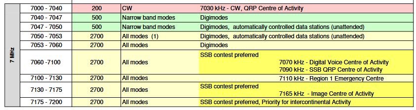
7 MHz Band (40 meters)
Status: primary.
Characteristics: one of the most active and versatile bands. During the day it allows regional connections, while at night it opens to the world thanks to long-distance ionospheric propagation (DX).
It’s widely used in CW, SSB and modern digital modes. In Italy the available portion ranges from 7000 to 7200 kHz.
Excellent compromise between distances and antenna ease.
10 MHz Band (30 meters)
Status: secondary, exclusive use in CW and digital modes.
Characteristics: intermediate band, quiet and silent.
Offers stable and predictable propagation, useful for international medium-long distance connections.
Much loved by CW and FT8 operators for its linearity and low interference from voice traffic.
14 MHz Band (20 meters)
Status: primary.
Characteristics: It has always been the “queen” band for long-distance connections, almost always active, with excellent daytime propagation and even nighttime openings during periods of high solar activity. Allows intercontinental connections with modest power. It’s one of the most popular bands for SSB, CW and FT8.
18 MHz Band (17 meters)
Status: primary.
Characteristics: “quiet” and less crowded band, with propagation similar to 20 m but less congested.
Ideal for those who love clean, low-noise DX connections. Often open even when 15 m is closed.
21 MHz Band (15 meters)
Status: primary.
Characteristics: typical daytime band, very dependent on the solar cycle.
With good ionospheric conditions, allows worldwide connections with minimal power and compact antennas.
It’s loved by contesters and digital experimenters.
24 MHz Band (12 meters)
Status: primary.
Characteristics: It’s a relatively new and not very frequented band, but capable of surprising openings during peaks of solar activity.
28 MHz Band (10 meters)
Status: primary.
Characteristics: has very variable performance based on solar activity. Closed during periods of low activity, during cycle peaks it allows long-distance connections with modest power and antennas. It’s the widest band and is used for experiments and beacons.
50 MHz Band (6 meters)
Status: secondary in Italy (primary in other countries).
Characteristics: nicknamed “the magic band”, for its unpredictability. Halfway between shortwave and VHF, it offers both ionospheric propagation (sporadic E, F2)* and direct line-of-sight. It can suddenly “open” to long distances, and for this reason it’s much loved by experimenters.
70 MHz Band (4 meters)
Status: experimental/secondary.
Characteristics: not universally assigned, but growing. Similar to 6 m, with very frequent sporadic-E2 openings. In Italy it’s subject to specific time-limited authorizations.
144–146 MHz Band (2 meters)
Status: primary.
Characteristics: first true VHF band, with mainly optical propagation. Ideal for local and regional connections, but capable of tropospheric or sporadic-E1 openings over hundreds of kilometers. Used in FM (repeaters, simplex), SSB, CW, satellites and digital (APRS, packet, beacons). It’s the meeting ground between technical and operational amateur radio.
430–440 MHz Band (70 cm)
Status: primary.
Characteristics: UHF band with line-of-sight propagation, but excellent reflectivity on obstacles and for connections in urban environments.
Used in FM, repeater links, direct connections, ATV, short-range and satellite digital modes. Very stable and with low noise, perfect for technical experiments and local links.
Propagation
Radio propagation is the physical phenomenon through which electromagnetic waves move from a transmitter to a receiver. Just as sound propagates through air or waves through water, radio signals propagate using different mechanisms.
Ionospheric propagation (Sky wave)
Ionospheric wave propagation, called skywave, is the main method for long-distance radio communications on HF bands. The part of the signal that is transmitted towards the sky is refracted (deflected) by the ionized layers of the upper atmosphere – the ionosphere – and sent back to Earth, allowing distances of thousands of kilometers to be covered with one or more “hops”.
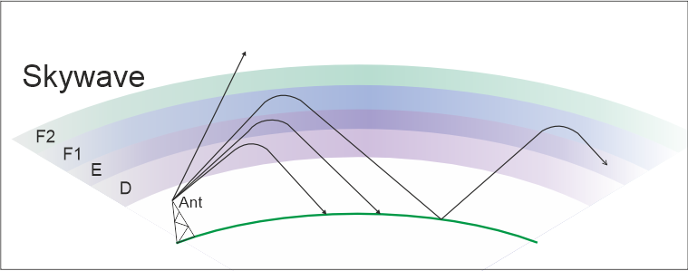
The ionosphere is composed of various layers of gases, ionized by solar activity, which change over time based on the amount of energy they receive from the Sun.
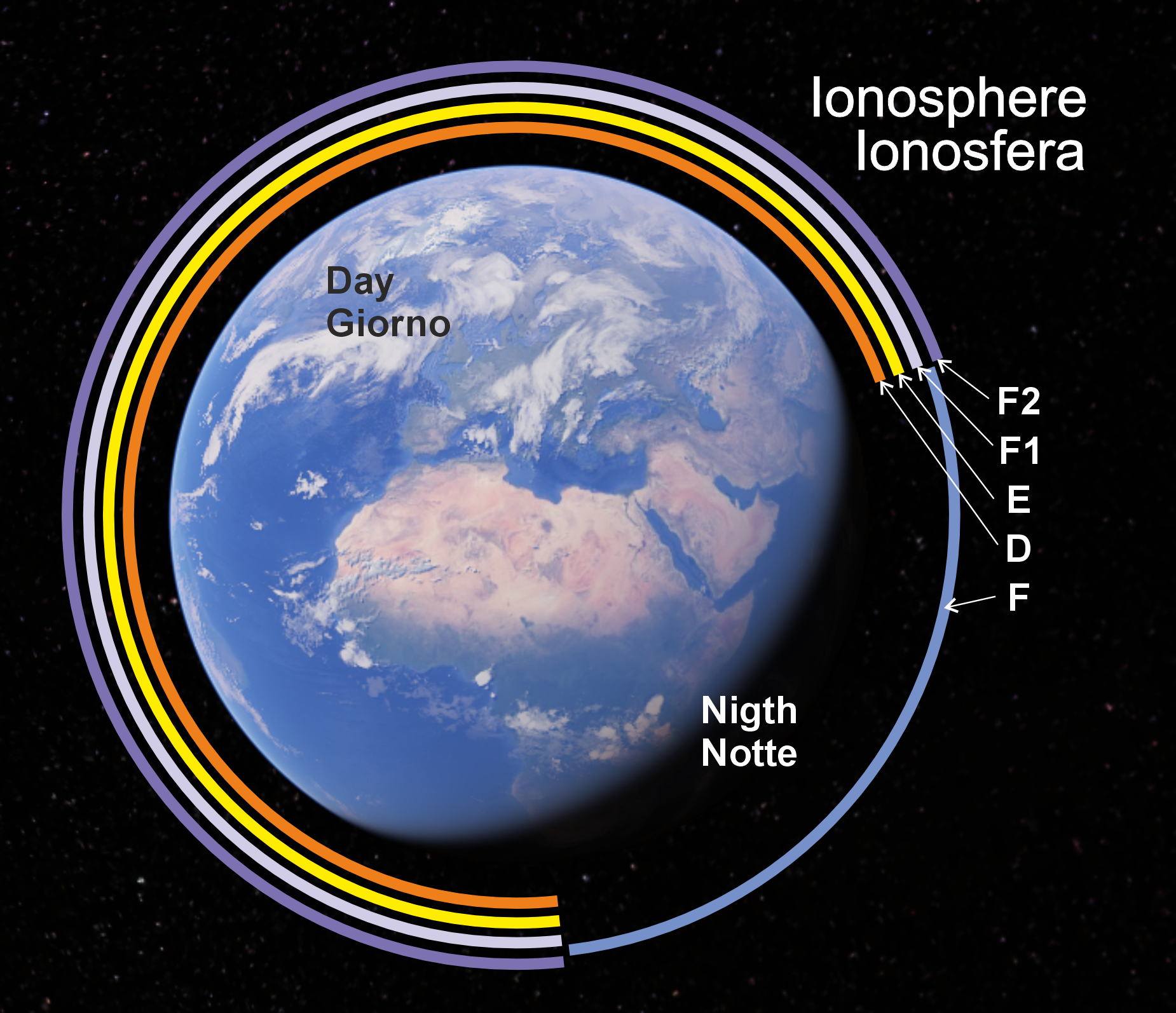
D Layer: is located at altitudes between 60 and 90 km, forms at dawn with sunrise and dissolves at sunset, gradually weakening until it disappears at night. It’s the lowest and densest layer, with low ionization, and has the effect of absorbing signals on the lower part of the HF spectrum (160 m, 80 m).
E Layer: is located at altitudes between 90 and 130 km, and is present mainly during the day. At night it weakens, but doesn’t disappear completely. It reflects well the medium-low bands (80 m, 40 m, 30 m), and is suitable for medium-distance communications (500–1500 km). Under particular conditions, very dense ionization clouds are generated that allow the reflection of much higher frequencies, even approaching UHF: this is the so-called sporadic E.
F1 Layer: is located at altitudes between 150 and 250 km. Contributes to propagation, but less than the F2 layer.
F2 Layer: is located at altitudes between 250 and 400 km. It’s the one that most contributes to long-distance connections, reflecting well frequencies above 10 MHz.
F Layer: at night the F1 and F2 layers merge into a single layer, located between 300 and 500 km. Reflects mainly frequency ranges below 10 MHz and allows longer hops thanks to the greater height.
The success of this type of propagation depends on the interaction of three key elements.
The first is the choice of frequency band. In effect, there’s a window of usable frequencies for each ionospheric condition. Frequencies that are too low are absorbed by the ionosphere, particularly by the D and E layers. Frequencies that are too high penetrate through the ionosphere and are lost in space. The maximum usable frequency for a given path is called the MUF (Maximum Usable Frequency).
The second is the radiation angle, or incidence, which is the angle at which the signal hits the ionosphere. It’s the parameter that determines the hop distance. Lower, grazing angles produce longer hops. Angles that are too low or too vertical can cause absorption or penetration respectively, interrupting propagation. This element is characteristic of various antenna types and how they are installed.
The third is ionization density, that is, the amount of charge in the ionospheric layers (D, E, F1, F2). It’s not a constant value, varying with the day/night cycle, seasons and the solar cycle (SSN, sunspot number, which is the number of sunspots). High density values (e.g. daytime, high SSN) favor higher HF bands (15 m, 12 m, 10 m). In case of low density (e.g. nighttime, low SSN) lower HF bands (80 m, 40 m) are more usable.
The difference between day and night is notable. During the day the ionospheric layers are well defined (D, E, F1, F2). The D layer strongly absorbs low bands (160 m, 80 m). The F2 layer is mainly responsible for long-distance communications, and the best bands are the medium and high ones (20 m, 17 m, 15 m).
At night the D and E layers almost completely disappear, the F1 and F2 layers merge into a single nighttime F layer, higher up. Absorption decreases, allowing the use of low bands (160 m, 80 m, 40 m), while the greater height of the F layer allows longer hops.
There are other elements to consider. One is multipath, a condition that allows the signal to reach its destination via different paths and with a different number of hops, causing fading (signal evanescence) due to interference. Another is so-called greyline propagation, consisting of brief windows of very efficient propagation that occur at dawn and dusk along the day/night transition line. Other rarer elements, which must also be taken into account, are the further elevation of the nighttime F layer in case of strong solar winds, which can increase the distance covered by a single hop to over 6000 km, and also skewed-path, in which the signal is deflected not only on the vertical plane, but also on the horizontal one – a phenomenon of interest to those who use directional antennas.
Forecasts
Solar activity, which determines the usability of our bands, is kept under close monitoring, and among the various parameters collected there are two key ones for understanding how things will go in the immediate future: SFI (Solar Flux Index) and Kp (planetary K-index). The SFI value determines the expected maximum usable frequency: with a simplified but effective formula, MUF (MHz) ≈ 0.15 × SFI. The Kp value is an index of propagation stability: the higher the value, the greater the instability, up to total closure with Kp > 5. Specialized applications exist that can estimate propagation trends towards a specific point on the Earth’s surface, in order to have an overview of the probability of making connections with specific stations.
Direct wave
At higher frequencies, signal propagation occurs by direct wave, with both transmitting and receiving antennas in sight of each other.
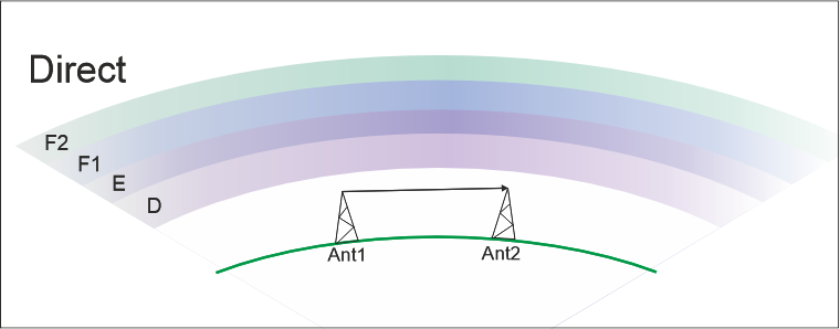
The direct wave (space wave or line-of-sight wave) is the component of the signal that travels along an almost straight path from transmitter to receiver. It typically operates from 30 MHz to microwaves, where ionospheric effects are negligible and the “optical” path is dominant. However, even in direct wave, the signal is never perfectly linear: it interacts with obstacles, surfaces and discontinuities. The main effects are reflection and diffraction, as well as scattering effects, which we’ll see later.
Reflection occurs when the signal encounters a surface large enough and smooth enough to bounce it, just as happens with light on a mirror or water. It occurs on the ground, especially if it’s wet or flat, on the sea surface, on building walls, glass facades, metal roofs, on mountains or wide slopes, on vehicles, towers, metal infrastructures. Reflection almost always creates multiple paths (multipath): the receiver receives both the direct wave and one or more reflected copies. Since these copies arrive with a different delay and amplitude, distortion and fading effects occur. This is the typical effect noticed when moving by car in the city: just moving a few meters is enough to see the signal level rise and fall. Reflection is very marked in urban environments and along paths close to the ground. In higher bands (UHF–SHF), where wavelengths are small, the phenomenon is even more evident.
Diffraction is the ability of the signal to bend around obstacles, it occurs because radio waves don’t follow a single geometric line, but are distributed in space and tend to spread. It’s a phenomenon that manifests itself, for example, on the edge of a hill or a relief that partially obstructs the link; on the edges of buildings, on roofs, rocky crests, marked slopes.
Diffraction allows the signal to be received even without perfect optical visibility. It’s thanks to diffraction that a VHF radio link can work even when the “edge” of a ridge slightly covers the line between the two antennas. The downside is that diffraction weakens the signal, even significantly, and the more the obstacle occupies the path, the more the signal drops. Going up in frequency, diffraction becomes much less effective.
For this reason in VHF certain routes work even without perfect visibility; in UHF it works much less; in microwaves (SHF) it practically doesn’t work and pure optical visibility is needed.
Scattering
Scattering is the phenomenon by which a radio signal, instead of continuing in a single direction, is dispersed in many directions when it encounters irregular surfaces, small obstacles or atmospheric non-uniformities.
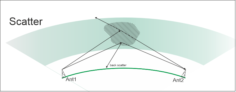
Unlike reflection, which is an orderly bounce on a smooth surface, and diffraction, which is a bending of the wave around obstacles, scattering is a disordered phenomenon, in which energy is randomly scattered. Scattering phenomena also manifest in terrestrial environments, but the most interesting ones for the radio amateur are mainly two.
Troposcatter (tropospheric scattering)
Troposcatter is linked to the troposphere: when a UHF or microwave signal crosses the upper layers of this atmospheric region, some inhomogeneities (turbulence, air density variations) “scatter” part of the radio energy downward. This mechanism allows connections over distances well beyond simple line-of-sight, typically up to a few hundred kilometers. From an operational point of view, high powers and high-gain directional antennas are used, since the fraction of “scattered” signal is reduced, but still sufficient to establish stable connections. The FT8 digital mode also lends itself well to troposcatter connections, provided the path isn’t excessively long and conditions remain relatively stable. It is in fact one of the most effective modes for making QSOs at the noise limit in VHF/432 MHz under weak scatter conditions.
Meteor scatter
Meteor scatter exploits the ionized trails produced by meteoroids when they penetrate the Earth’s atmosphere (typically between 80 and 100 km altitude). When these trails are “illuminated” by a radio signal, part of the wave can be reflected or diffused toward Earth, making reception possible over distances otherwise unreachable with a direct path. The length – and therefore the duration – of the trail depends on the size of the meteoroid. It’s a technique used especially in VHF, with very short-duration connections, on the order of a few seconds. Propagation is more systematically exploitable during meteor showers, but there’s always a certain margin of sporadic activity even outside of them.
An application example is the French GRAVES radar system (Grand Réseau Adapté à la Veille Spatiale), which transmits a fixed carrier at 143.05 MHz with great power (not made public, as it’s covered by military secrecy). It’s relatively simple to receive, in much of Europe – including Italy – the echoes of its signals reflected by objects passing through its observation field, from which information about the object that generated the trace can be obtained.
Ground wave
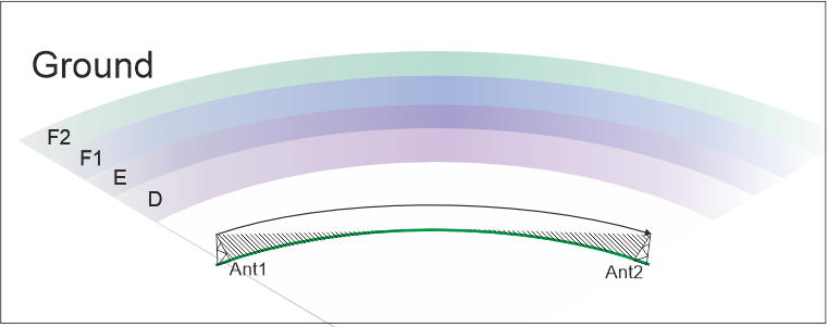
The ground wave is a propagation mode typical of low and medium frequencies (LF, MF and partly HF), in which the radio signal leans on and propagates following the Earth’s curvature. Unlike the direct wave (line-of-sight) or the wave reflected by the ionosphere, the ground wave exploits interaction with the ground: the Earth’s surface guides the electromagnetic wave, which gradually attenuates due to ground conductivity and dielectric losses.
This form of propagation is particularly useful because it allows significant distances to be reached even without ionospheric reflections, ensuring stable and continuous coverage, especially during the day when ionospheric waves are less reliable. Attenuation depends on frequency (the lower the frequency, the greater the range) and the nature of the terrain (conductive soils such as marine ones favor propagation, while rocky or dry terrain attenuates it).
A very well-known case of ground wave propagation is the DCF77 signal, a German transmitter located in Mainflingen, near Frankfurt. It operates on 77.5 kHz and transmits a time synchronization signal, encoded so that it can be received by radio-controlled clocks in much of Europe. Thanks to the ground wave, the signal spreads stably for hundreds of kilometers, covering vast areas without needing ionospheric reflections. The low frequency guarantees excellent penetration and continuity, even in urban environments. It’s an example that shows how the ground wave is ideal for continuous and reliable broadcast services, where precision and signal availability are fundamental.
Another crucial use of ground wave concerns VLF (Very Low Frequency, 3–30 kHz) systems used to communicate with submarines. Very low frequencies are used, with wavelengths of kilometers. The ground wave at these frequencies has enormous range, and in addition to following the Earth’s curvature it can also partially penetrate seawater, allowing submarines underwater to receive orders and messages without surfacing. Ground wave propagation, in this case, is vital: no other mode allows maintaining a reliable connection with submerged units on a global scale.
 Info
Info1) The general IARU bandplan for region 1 can be downloaded here.